Experimental Study on Liquid Film Behavior with Asymmetric Air Flow - - PDF document

experimental study on liquid film behavior with
SMART_READER_LITE
LIVE PREVIEW

Experimental Study on Liquid Film Behavior with Asymmetric Air Flow - - PDF document

Transactions of the Korean Nuclear Society Virtual Spring Meeting July 9-10, 2020 Experimental Study on Liquid Film Behavior with Asymmetric Air Flow under Emergency Core Coolant Bypass Condition Chi-Jin Choi and Hyoung Kyu Cho * Nuclear


slide-1
SLIDE 1

Experimental Study on Liquid Film Behavior with Asymmetric Air Flow under Emergency Core Coolant Bypass Condition

Chi-Jin Choi and Hyoung Kyu Cho * Nuclear Thermal-Hydraulic Engineering Laboratory, Seoul National University 1 Gwanak-ro, Gwanak-gu, Seoul 08826

*Corresponding author:chohk@snu.ac.kr

  • 1. Introduction

The liquid film in the nuclear reactor systems has been regarded as of major importance in reactor safety. Especially, the emergency core coolant (ECC) in the form of the liquid film at the upper reactor vessel (RV) downcomer serves to cool the core during the reflood phase of a loss of coolant accident (LOCA). However, in the nuclear reactor that adopts direct vessel injection of the ECC, the transverse steam flow from the intact cold legs makes some portion of the ECC film bypasses toward the broken cold leg. As the ECC bypass increases, it contributes less to the reactor cooling. Thus, an accurate prediction of the film behavior is important to determine the adequate ECC injection rate to ensure nuclear reactor safety. Meanwhile, there has been an attempt to simulate LOCA using a thermal-hydraulic code, CUPID [1, 2] developed at Korea Atomic Energy Research Institute. However, the validation of the simulation result has not yet been carried out sufficiently due to a lack of local experimental data under various conditions. As for the ECC bypass phenomenon, some experimental works have measured the ECC bypass flow rate [3-5], but there have been few studies on investigating the flow behavior

  • locally. Accordingly, we have recently performed an air-

water two-phase flow experiment describing the ECC bypass phenomenon and measured the local liquid film thickness [6]. In this previous work, the air flow inside the RV downcomer was assumed to be formed symmetrically around the broken cold leg. However, in the case of actual RV, three intact cold legs are arranged asymmetrically with respect to the broken cold leg. This configuration allows the gas not to flow symmetrically and might lead the hydraulic behaviors that have not been examined before. The present study aims to take a step toward understanding the liquid film behavior at the upper part

  • f the RV downcomer. To support this objective, an

experiment was conducted with 1/10 reduced scale downcomer annulus under asymmetric air flow

  • conditions. Then, the local liquid film thickness was

measured by the developed sensor based on the electrical conductance method. The ECC bypass fraction was also

  • btained under various flow conditions.
  • 2. Sensor Development

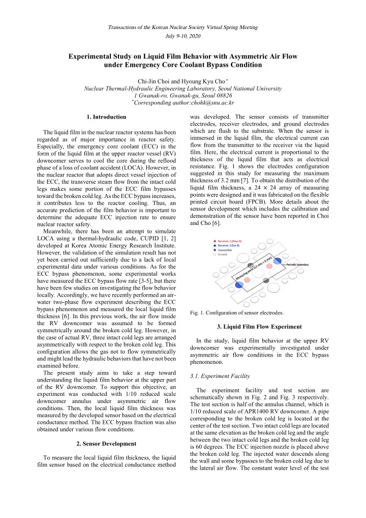
To measure the local liquid film thickness, the liquid film sensor based on the electrical conductance method was developed. The sensor consists of transmitter electrodes, receiver electrodes, and ground electrodes which are flush to the substrate. When the sensor is immersed in the liquid film, the electrical current can flow from the transmitter to the receiver via the liquid

  • film. Here, the electrical current is proportional to the

thickness of the liquid film that acts as electrical

  • resistance. Fig. 1 shows the electrodes configuration

suggested in this study for measuring the maximum thickness of 3.2 mm [7]. To obtain the distribution of the liquid film thickness, a 24 × 24 array of measuring points were designed and it was fabricated on the flexible printed circuit board (FPCB). More details about the sensor development which includes the calibration and demonstration of the sensor have been reported in Choi and Cho [6].

  • Fig. 1. Configuration of sensor electrodes.
  • 3. Liquid Film Flow Experiment

In the study, liquid film behavior at the upper RV downcomer was experimentally investigated under asymmetric air flow conditions in the ECC bypass phenomenon. 3.1. Experiment Facility The experiment facility and test section are schematically shown in Fig. 2 and Fig. 3 respectively. The test section is half of the annulus channel, which is 1/10 reduced scale of APR1400 RV downcomer. A pipe corresponding to the broken cold leg is located at the center of the test section. Two intact cold legs are located at the same elevation as the broken cold leg and the angle between the two intact cold legs and the broken cold leg is 60 degrees. The ECC injection nozzle is placed above the broken cold leg. The injected water descends along the wall and some bypasses to the broken cold leg due to the lateral air flow. The constant water level of the test

Transactions of the Korean Nuclear Society Virtual Spring Meeting July 9-10, 2020

slide-2
SLIDE 2

section makes the air only flows to the broken cold leg. The two developed sensors are attached to the half side

  • f the inner wall to measure the liquid film thickness.
  • Fig. 2. Simplified scheme of the test facility.
  • Fig. 3. Simplified scheme of the annulus test section.

3.2. Experiment Conditions The boundary conditions were determined by the simulation results of the APR1400 during a LOCA [8]. To examine the effect of asymmetric air flow on the liquid film behavior, the ratio of the air inlet velocity ( ,: , ) was varied from 1.00:1.00 to 1.33:0.67 assumed to be the most extreme conditions in an actual RV downcomer. The entire test conditions are presented in Table 1.

Table I: Experiment Conditions

Water inlet velocity   [m/s] 2.32×10⁴ 0.63 3.28×10⁴ 0.89 Air velocity , , [m/s] ,:, 1.00×10⁵ 20 1.00:1.00 1.20:0.80 1.33:0.67 1.10×10⁵ 22 1.20×10⁵ 24 1.30×10⁵ 26 Because the liquid film thickness sensors only covered the half side of the test section, the test was carried out twice for each case alternating two different inlet air velocities to be able to obtain the entire distribution of the liquid film thickness.

  • 4. Results and Discussion

4.1. Time-averaged Liquid Film Thickness

  • Fig. 4 shows the time-averaged liquid film thicknesses

versus the ratio of air inlet velocity while the outlet velocity is maintained to 24 m/s. As depicted in Fig. 4(a), the spreading width of the liquid film changes depending

  • n the air flow. When the air velocities at two inlets are

the same, the liquid film flow becomes symmetrically narrower toward the center due to the interfacial friction

  • force. If this balance of the air flow breaks, the liquid film

boundary on the left side where the air velocity is relatively faster gets closer to the center. On the other hand, the liquid film boundary on the right side is shifted farther from the center. The air inlet conditions also affect the local liquid film thickness. When the air velocity ratio is 1.33:0.67, the liquid film near the center gets thicker, which is caused by the shifted liquid film boundary and enhanced radial air flow on the left side. When the water velocity becomes larger as shown in Fig. 4(b), the liquid film spreads wider and overall liquid film gets thicker. Although the effect of the asymmetric air flow on the liquid film flow is not as significant due to the increased water flow rate, the overall trend of change in the liquid film boundary and thickness is similar to the results in Fig. 4(a).

  • Fig. 4. Time-averaged liquid film thickness with different ratios
  • f air inlet velocity when , = 24 m/s: (a)  = 0.63 m/s, (b)

 = 0.89 m/s.

The quantitative changes in the liquid film thickness are shown in Fig. 5. In the figure, the circumferential profiles of the liquid film thickness were plotted for three elevations (z=-72 mm, z=-225 mm, z=-243 mm). At the upper part of the liquid film flow (z=-72 mm), there is little difference in the film thickness according to the air flow conditions. At the lower part of the liquid film flow

Transactions of the Korean Nuclear Society Virtual Spring Meeting July 9-10, 2020

slide-3
SLIDE 3

(z=-225 mm, z=-243 mm), the thickness profiles change as already confirmed in Fig. 4.

  • Fig. 5. Time-averaged liquid film thickness with different ratios
  • f air inlet velocity when , = 24 m/s: (a)  = 0.63 m/s, (b)

 = 0.89 m/s.

The air flow affects the interface of the liquid film as

  • well. The strong air flow induces the unstable wavy film

and droplets formation from the film break-up. This entrainment is a major mechanism of the ECC bypass phenomenon, and to investigate local characteristics such as the fluctuation of the liquid film can provide an adequate understanding of the phenomenon. In this point

  • f view, the degree of the liquid film fluctuation is

illustrated in Fig. 6. It is expressed as the standard deviation of the liquid film thickness measured during 10

  • seconds. Under the symmetric air flow condition, the

fluctuation reveals strong at the thick liquid film

  • boundary. The reason for the thick boundary in the upper

liquid flow being unstable is that the boundary consists

  • f liquid falling under gravity after its radial flow is

terminated; the liquid film descends flowing around the boundary while collecting more liquid [9]. However, the large fluctuation at the lower liquid flow is caused by the entrainment, which contributes to an increase in the ECC

  • bypass. Under the asymmetric air flow condition, the

fluctuation on the right side shows a distinct increase. The reason for this is might be the unbalance of air inlet flow that leads to unstable air flow inside the test section and it makes the liquid film boundary rolls from side to

  • side. In the lower part adjacent to the broken cold leg, the

increase of the fluctuation was confirmed near the thick film.

  • Fig. 6. The fluctuation of liquid film thickness when  = 0.63

m/s and , = 24 m/s.

4.2. Emergency Core Coolant (ECC) Bypass Fraction In the experiment, the ECC bypass fraction was

  • btained by measuring the water injection rate and

penetration rate through the bottom of the test section as follows. Bypass fraction = 1 −

 ̇ 

  

 ̇ 

(1) In Fig. 7, the ECC bypass fraction with different ratios

  • f air velocities was presented versus the air outlet
  • velocity. When the air outlet velocity is less than 24 m/s,

the bypass fraction increases as the asymmetry of the air flow gets stronger. If the symmetric air inlet flow changes to the asymmetric condition, the variance of the liquid film boundary would be as in Fig. 8. On the left side where the air flows faster, the liquid film boundary gets closer to the center, which induces the increase of the ECC bypass. On the right side, the liquid film boundary gets wider with decreased air flow, which contributes to a decrease of the ECC bypass. Although those two conflicting behaviors of the liquid flow exist, enhancing the ECC bypass on the left side is dominant, so it produces the increment of overall ECC bypass

  • fraction. When the air outlet velocity reaches 26 m/s,

more than 70% of the injected ECC was bypassed out and the bypass fraction decreases as increasing the asymmetry of the air flow. This is because the spreading width of the liquid film on the left side is sufficiently narrowed toward the broken cold leg and most of it bypasses due to the strong air flow. That means the effect

  • f the increased air flow on raising the ECC bypass is

nearly saturated in this condition. Therefore, the wider width of the liquid film caused by the decreased air flow

  • n the right side affects the ECC bypass more, which

makes overall bypass decreases.

Transactions of the Korean Nuclear Society Virtual Spring Meeting July 9-10, 2020

slide-4
SLIDE 4
  • Fig. 7. ECC bypass fraction when  = 0.63 m/s.
  • Fig. 8. Effect of shifted liquid film boundary on ECC bypass.
  • 5. Conclusion

The experimental work was performed to investigate the effect of asymmetric air flow on the ECC bypass

  • phenomenon. The measurement results showed that the

asymmetry of air flow leads to asymmetric boundary shape of the liquid film flow and thick liquid film near the broken cold leg. The effect of the air flow on the liquid film surface also could be confirmed that asymmetric air flow raises the liquid film fluctuation near the center with active entrainment phenomenon. The measurement results of ECC bypass fraction well reflected theses film behavior charateristics. At the highest air velocity, however, the stronger the asymmetry of air flow is supplied, the lower the ECC bypass fraction appears because the liquid on the side where the air velocity is relatively higher shows complete bypass and the bypass fraction is determined by the liquid film behavior on the lower velocity side. This study leads to a deep understanding of the ECC bypass phenomenon under asymmetric air flow

  • conditions. The insights from the experiment results can

be used to validate the thermal-hydraulic simulation codes and to improve the interfacial closure relations for the two-fluid model implemented in the code. ACKNOWLEDGMENT This work was supported by the National Research Foundation (NRF) of Korea funded by the MSIP (No. NRF-2018M2B2A9065744/0666-20200008). REFERENCES

[1] Korea Atomic Energy Research Institute, CUPID Code Manuals Vol 1: Mathematical Models and Solution Methods Version 2.2, 2018. [2] H. Y. Yoon, I. K. Park, J. R. Lee, Y. J. Cho, S.-J. Lee, H. K. Cho, J. J. Jeong, MULTI-SCALE AND MULTI-PHYSICS NUCLEAR REACTOR SIMULATION FOR THE NEXT GENERATION LWR SAFETY ANALYSIS, in: Proceedings

  • f the 18th International Topical Meeting on Nuclear Reactor

Thermal Hydraulics (NURETH-18), Portland, OR, 2019, pp. 6026–6039. [3] MPR-1329, Summary of results from the UPTF downcomer injection/vent valve separate effects test: Comparison to previous scaled tests, and application to Babcock & Wilcox pressurized water reactors, MPR Associates, September 1992. [4] H. K. Cho, B. J. Yun, C.-H. Song, G.C. Park, Experimental study for multidimensional ECC behaviors in downcomer annuli with direct vessel injection mode during the LBLOCA reflood phase, Journal of nuclear science and technology, Vol. 42, p.549-558, 2005. [5] T. S. Kwon, B. J. Yun, D. J. Euh, I. C. Chu, C.-H. Song, Multi-dimensional mixing behavior of steam-water flow in a downcomer annulus during LBLOCA reflood phase with a DVI injection mode, Nuclear Technology, Vol. 143, p.57-64, 2003. [6] C.-J. Choi, H. K. Cho, Investigation on emergency core coolant bypass with local measurement of liquid film thickness using electrical conductance sensor fabricated on flexible printed circuit board, International Journal of Heat and Mass Transfer, Vol.139, p.130-143, 2019. [7] J.-H. Yang, H.-K, Cho, S. Kim, D.-J. Euh, G.-C. Park, Experimental study on two-dimensional film flow with local measurement methods, Nuclear Engineering and Design, Vol. 294, p.135-151, 2015. [8] Korea Atomic Energy Research Institute, Post-test Analysis for the APR1400 LBLOCA DVI Performance Test Using MARS, KAERI/TR-2137/2002, 2002. [9] T. Wang, D. Faria, L.J. Stevens, J.S.C. Tan, J.F. Davidson, D.I. Wilson, Flow patterns and draining films created by horizontal and inclined coherent water jets impinging on vertical walls, Chemical Engineering Science, Vol. 102, p.585- 601, 2013. Transactions of the Korean Nuclear Society Virtual Spring Meeting July 9-10, 2020