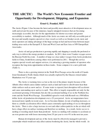
EME 2016 Venice - Italy Chapter II Signal polarity in V/UHF bands - PowerPoint PPT Presentation
EME 2014 Parc du Radome Pleumeur Bodou - France Chapter I Ionospheric interactions with EME signals EME 2016 Venice - Italy Chapter II Signal polarity in V/UHF bands By Giorgio IK1UWL and Flavio IK3XTV Background Chapter I
EME 2014 – Parc du Radome – Pleumeur Bodou - France Chapter I Ionospheric interactions with EME signals EME 2016 – Venice - Italy Chapter II Signal polarity in V/UHF bands By Giorgio IK1UWL and Flavio IK3XTV
Background • Chapter I • In 2014, in France, we showed you, besides QSB origins, Faraday’s behavior on 2 m. • All computations and graphs were made with an Excel sheet, complete with the relevant formulas. • Results were checked for congruence with real decodes. • We have a big library of stations pairs
Our Excel sheet Steps: 1 2 3 Moon Sked
Results for each station SP4MPB (tx) PA3FPQ (rx) Wave going up Wave coming back
Final results in 2 m • Differences in evolution of Ka and of cosFM give different evolution to Faraday rotation of each station. • Final polarity is algebraic sum of individual rotations and offsets.
Chapter II • Using this Excel sheet library, we intend to expand on the polarity issue for the four V/UHF bands. • Polarity of an incoming signal is the sum of Spatial Offset and Faraday rotation. • Spatial Offset is dependent only on the relative location of the stations. • Faraday is dependent on frequency, ionosphere’s density, and on Moon’s position.
From our library: Spatial Offsets • SP4MPB rxed by PA3FPQ on 2 m: Calculated Polarity • With a simple shift: Spatial Offset between SP4MPB and PA3FPQ 12,0 Spatial Offset 10,0 8,0 6,0 4,0 2,0 0,0 10:00 10:30 11:00 11:30 12:00 12:30 13:00 13:30 14:00 14:30 15:00 15:30 16:00 16:30 17:00 17:30 18:00 18:30
Spatial Offset Angle between earth’s axis and polarization vector • P =Polar offset • From a paper of N1BUG: • P =arctg((sin Lat *cos El -cos Lat *cos Az *sin El )/cos Lat *sin Az ) • Spatial Offset = P1 – P2 • Same for all bands, variables are Lat, Az, El • Spatial Offset increases with distance • SP4MPB 1000 km east of PA3FPQ TI2SW 9000 km west of IKUWL • from 2°,8 to 10° from 74°,8 to 117°,7 12 10 8 6 gradi 4 2 0 10:00 10:30 11:00 11:30 12:00 12:30 13:00 13:30 14:00 14:30 15:00 15:30 16:00 16:30 17:00 17:30 18:00 18:30 utc
Offset: change with distance and direction Northern stations Southern stations 50,0 150 RI1FJL 4507 km 9X0EME 5540 km 40,0 100 30,0 5N0EME 3860 km ZS6OB 50 20,0 LA8KV 2113 km 7988 km Offset (°) 10,0 0 Offset (°) 0,0 PA1T 1050 km 5A7A 1300 km -50 -10,0 -20,0 -100 -30,0 UTC -150 -40,0 UTC 11:00 11:30 12:00 12:30 13:00 13:30 14:00 14:30 15:00 15:30 16:00 16:30 17:00 17:30 18:00 18:30 19:00 19:30 20:00 20:30 21:00 21:30 11:00 12:00 13:00 14:00 15:00 16:00 17:00 18:00 19:00 20:00 21:00 22:00 23:00 Reference: IK1UWL - JN33vt 90 RA0JT 8070 Km 80 70 RV9UV 5574 km 60 Offset (°) 50 UA9SL 3587 km 40 30 20 10 TA1D 1740 km 0 11:00 11:30 12:00 12:30 13:00 13:30 14:00 14:30 15:00 15:30 16:00 16:30 17:00 17:30 18:00 18:30 19:00 19:30 20:00 20:30 21:00 21:30 Western stations Eastern stations
From our library: Conversion to other bands • In our sheet, column L (Rotaz. °) calculates the Faraday rotation: 1,14*F*cosFM*STEC • 1,14 is k/f 2 for 144 MHz (with k=2,36*10 16 ) • One needs only to substitute 1,14 with the coefficient for another band: 6m 2m 70 cm 23 cm 9,46 1,14 0,127 0,0123 • Our library gets quadrupled.
4 bands (6 m, 2 m, 70 cm, 23 cm) Total rotation ( Faraday + Spatial Offset ) for SP4MPB 1296 MHZ received by 432 MHZ PA3FPQ on four 144 MHZ bands. Big polarity changes only in the VHF bands. Note: curves refer to an unperturbed ionosphere 50 MHZ
VHF bands, unperturbed ionosphere • In VHF, polarity is determined mainly by Faraday rotation which is much bigger than Spatial Offset . = (k/f 2 ) * (F*cosFM) * (k a *VTEC) • • Factors influencing Faraday • Band (rotation inversely proportional to f 2 ) • During the Moon Pass (for an unperturbed ionosphere): • 0 < cos FM < 1 since 90°> FM > 0° • 1 < k a < 3,7 4 < Vertical T otal E lectron C ontent < 40 TECU (10 16 electrons/m 2 ) •
VHF bands, turbulent ionosphere • Superimposed on the average evolution of Faraday rotation during a Moon pass, there can be a more quicker fluctuation due to the effect of ionospheric winds and plasma tubes. • Winds cause undulations and waves (TIDs), so free electron density varies in space and time, causing rotation fluctuations. • Australian scientist of the University of Sydney , Cleo Loi, has made the very interesting discovery of plasma tubes in Earth's magnetosphere. These structures are important because they cause signal distortions that could affect trans-ionospheric communication Recent discovery of Plasma tubes
VHF, 50 MHz band Ts 3600 °K • Faraday rotates thousands of degrees, so spatial offset is negligible
Effect of rotation speed on a JT65 qso • Hypothesis: signal level 3 dB above minimum decodable when polarity 0° • With polarity 90° decode not possible • With polarity 45° degradation is 3 dB • So only when polarity is between 45° and -45° decode is possible. • How many 1’ periods occur in 180° of rotation?
VHF, 144 MHz band Ts 300 °K • Near station (1000 km) Far station (9000 km) • SP4MPB – PA3FPQ TI2SW – IK1UWL • Faraday rotates hundreds of degrees, so overrides spatial offset also when it is big due to distance. • V-H-V transitions with typically a 30 to 60 minute period.
UHF bands • In the UHF bands the dominant factor becomes spatial offset, which can reach and pass half turn (in which case the supplement counts since phase does not count) . • Distance between stations has the biggest influence. SP4MPB – PA3FPQ
UHF, 432 MHz band Ts 85 °K Near station Far station H Pol. rotation at 432 MHz Faraday rotation Spatial Offset SP4PMB – PA3FPQ 1000 km TI2SW – IK1UWL 9000 km W • Faraday rotates only tens of Pol. rotation at 432 MHz Faraday rotation degrees, and is comparable to Spatial Offset V spatial offset. • Spatial offset is the biggest factor for far stations. V • V-H-V transitions are few and far apart. ZZ6OB – IK1UWL 8000 km S
UHF, 1296 MHz band Ts 68 °K Near station Far station TI2SW-IK1UWL 9000 km W SP4MPB – PA3FPQ 1000 km • Faraday rotates only some degrees. • Spatial offset becomes the dominant factor. • If circular pol. is not used, some control of polarization is useful. ZS6OB-IK1UWL 8000 km S
UHF, 1296 MHz band Ts 68 °K
VHF/UHF bands overview • VHF bands are dominated by Faraday, UHF bands are dominated by Spatial Offset • Going from 6 m to 23 cm, polarity changes with decreasing speed. • From peaks in the order of 1200°/h on 6m (because of Faraday), we tend towards 10°-20°/h on 23 cm (due to Spatial Offset). • So when single polarity of the receiving antenna is in use, favorable and unfavorable periods increase in length and decrease in number. • Our Excel sheet has allowed us to give numbers and orders of magnitude to characteristics qualitatively known of these bands for single polarity antennas.
Chapter II - 2016 Chapter I - 2014 • Thanks for the attention. • We are glad meeting you all again.
Recommend


More recommend
Explore More Topics
Stay informed with curated content and fresh updates.