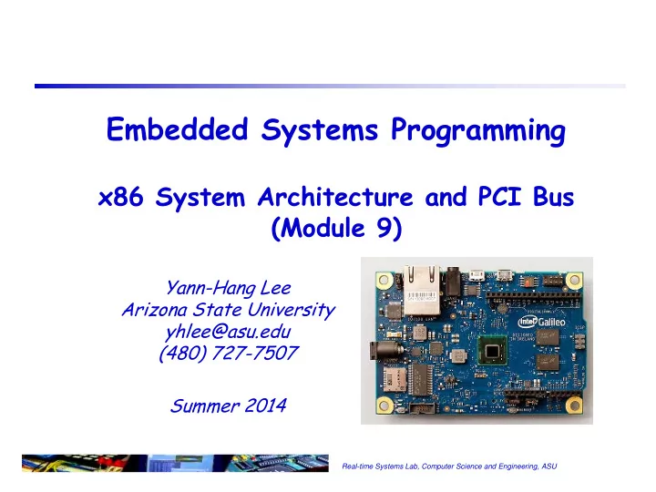

Embedded Systems Programming x86 System Architecture and PCI Bus (Module 9) Yann-Hang Lee Arizona State University yhlee@asu.edu (480) 727-7507 Summer 2014 Real-time Systems Lab, Computer Science and Engineering, ASU
Interrupt and APIC Interrupt in 8086 Two pins: NMI and INTR Interrupt Acknowledge Cycle to fetch the interrupt vector number from 8259 APIC In Pentium and P6 processors Receives interrupts and send to core for handling APIC bus: bi-directional data signals (APICD[1:0]) and clock (APICCLK) Inter-processor interrupt messages for multi-processor systems static and dynamic (based on the priority of executing tasks) distribution 1 Real-time Systems Lab, Computer Science and Engineering, ASU
Hardware Initialization and Reset Reset processor state EIP=0000FFF0H, CS=F000H(segment) and FFFF0000H (base) Disable paging, cache, and in real-address mode Execute the first instruction at physical address FFFFFFF0H . The EPROM containing the software initialization code or BIOS should be located at the upper memory space (including this address) Run in real-mode, invalidate the TLBs, set up a GDT for selector 0x08 (code) and 0x10 (data), switch to protected mode Start other components on motherboard (FPU, APIC, southbridge, etc.) 2 Real-time Systems Lab, Computer Science and Engineering, ASU
Typical x86 System Architecture Chipset System North Bridge Processor Memory Host Bus (PSB) South Bridge 100/133/200MHz Firmware Hub 64-bit AGP Bus Host Clock Various chipsets available North Clock PCI Clock Bridge from Intel to meet Gen (MCH) USB Clock Hublink Clock performance requirements HubLink Bus SM Bus FSB, DMI/Hub interface CNR South System control hub (SCH) Bridge (ICH) PCI Bus – GMCH and ICH are merged 33 MHz 32-bit into one chip LAN LPC Bus Audio Mouse USB Keybrd SIO FWH IDE Floppy Parallel Serial 3 Real-time Systems Lab, Computer Science and Engineering, ASU
Host Bridge in Quark A central hub that routes transactions to and from Quark CPU core, DRAM controller, and other functional blocks. CPU core PCI devices via MMIO and IO accesses 4 Real-time Systems Lab, Computer Science and Engineering, ASU
PCI Bus Release 2.1 -- 66MHz, 32-bit and 64-bit connectors. 3.3V or 5V based on PCI chip set’s buffer/drivers 1 12,13 50,51 62 94 3.3V key 5V key 64-bit portion Agent, bus master (initiator) and slave (target) Bus transaction : bus masters issue requests ⇒ arbitration ⇒ bus grant issues address and command and begins a cycle frame (transaction) memory, I/O, configuration read/write commands a target is selected (device select) it is ready to complete the data transfer phase 5 Real-time Systems Lab, Computer Science and Engineering, ASU
PCI Bus Signals PCI master device AD[63:32] CLK C/BE[7:4] FRAME REQ64 IRDY ACK64 TRDY DEVSEL Misc STOP control INT REQ C/BE[3:0] BIST signals Error AD[31:0] reporting A typical PCI read transaction REQ GNT RST 6 Real-time Systems Lab, Computer Science and Engineering, ASU
PCI Bus Operation Address phase At the same time, initiator identifiers target device and the type of transaction The initiator assert the FRAME# signal Every PCI target device latch the address and decode it Data Phase Number of data bytes to be transformed is determined by the number of Command/Byte Enable signals asserted by initiator Both of initiator and target must be ready to complete data phase IRDY# and TRDY# used Transaction completion and return of bus to idle state By deasserting the FRAME# but asserting IRDY# When the last data transfer has completed the initiator returns the PCI bus to idle state by deasserting IRDY# 7 Real-time Systems Lab, Computer Science and Engineering, ASU
PCI Commands C/BE[3::0]# Command Type Address and data phases 0000 Interrupt Acknowledge PCI allows the use of up to 16 0001 Special Cycle different 4-bit commands 0010 I/O Read Configuration commands 0011 I/O Write 0100 Reserved Memory commands 0101 Reserved I/O commands 0110 Memory Read Special-purpose commands 0111 Memory Write A command is presented on the 1000 Reserved C/BE# bus by the initiator 1001 Reserved during an address phase (a 1010 Configuration Read 1011 Configuration Write transaction’s first assertion of 1100 Memory Read Multiple FRAME#) 1101 Dual Address Cycle 1110 Memory Read Line 1111 Memory Write and Invalidate 8 Real-time Systems Lab, Computer Science and Engineering, ASU
Supplementary Slides Real-time Systems Lab, Computer Science and Engineering, ASU
Interrupt Handling IO APIC delivers interrupt message to local APIC Programmable vector number for each interrupt source Implied priority based on vector number local APIC determines when to service the interrupt relative to the other activities of the processor priority = vector / 16 Locate gate from IDT Far call to the handler (SS, ESP), EFLAGS, CS, EIP, and Error code are saved in stack 10 Real-time Systems Lab, Computer Science and Engineering, ASU
Message Bus Register Access Indirect access via PCI configuration space Message Bus Control Reg. (MCR) - PCI[B:0,D:0,F:0]+D0h Message Data Reg. (MDR) - PCI[B:0,D:0,F:0]+D4h Message Control Reg. eXtension (MCRX) - PCI[B:0,D:0,F:0]+D8h Uses the MCR/MCRX as an index register and MDR as the data register. Writes to the MCR trigger message bus transactions MCR description Field MBPR Bits OpCode (typically 10h for read, 11h for write) 31:24 Port 23:16 Offset/Register 15:08 Byte Enable 07:04 11 Real-time Systems Lab, Computer Science and Engineering, ASU
PCI Optimizations and Additional Features Push bus efficiency toward 100% under common simple usage Bus parking retain bus grant for previous master until another makes request granted master can start next transfer without arbitration Arbitrary burst length initiator and target can exert flow control with xRDY discount with STOP (abort or retry, by target), FRAME (by master) and GNT (by arbiter) Delayed (pended, split-phase) transactions free the bus after request to slow device Additional Features Interrupts: support for controlling I/O devices Cache coherency: support for I/O and multiprocessors Locks: support timesharing, I/O, and MPs Configuration Address Space (plug and play) 12 Real-time Systems Lab, Computer Science and Engineering, ASU
Recommend
More recommend