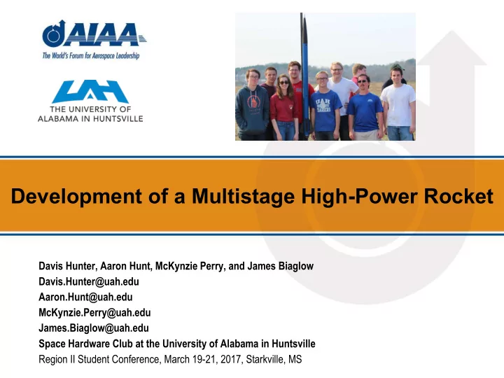

Development of a Multistage High-Power Rocket Davis Hunter, Aaron Hunt, McKynzie Perry, and James Biaglow Davis.Hunter@uah.edu Aaron.Hunt@uah.edu McKynzie.Perry@uah.edu James.Biaglow@uah.edu Space Hardware Club at the University of Alabama in Huntsville Region II Student Conference, March 19-21, 2017, Starkville, MS
Project URSA The Team: • Project Goal Manufacturing Liaisons Design, manufacture, • Sparky Shelton James Biaglow test, and fly a high Team Manager Nick Jordan powered rocket with Kyle Renfroe two stages to at least Davis Hunter Daniel Dorey 30,000 feet Chief Engineer Lower Stage Upper Stage McKynzie Perry Aaron Hunt Subsystem Lead Subsystem Lead Brendan Luke Mike Zaluki Jacob Zilke 2
Concept of Operations Initial Altitude Max. Velocity 3 4 5 # Event (feet) (ft/s Mach#) Combined 6 1 0 3,370 0.93 a Powered Ascent 2 2 Separation 2,750 3,000 0.83 6b 3 Initial Coast 3,000 3,000 0.83 2nd Stage Powered 4 6,650 6,330 1.77 Ascent 7 1 5 Coast to Apogee 11,000 6,200 1.74 6a Sustainer Deploy 31,200 175 . Booster 6b 6,250 94 . Deploy 7 Main Deploy 1,000 ~25 . 3
System Overview • Full System ▪ Total Length - 144 in ▪ Total Mass - 16,318 g ▪ Simulated Apogee - 31,232 ft ▪ Simulated Top Speed - 6,330 ft/s (Mach 1.77) ▪ Maximum Acceleration - 20.1 G 144” 70” 74” 4
Airframe Overview • Nose Cone ▪ Von Kármán Profile ▪ Section of Sears-Haack Body ▪ Optimized for Supersonic Flight • Body Tubes ▪ G12 Fiberglass ▪ Sustainer - 0.1 inch thickness ▪ Booster - 0.125 inch thickness 5
Airframe Overview Cont. • Fins • Boattail ▪ Carbon Fiber Fins ▪ 3D Printed ABS ▪ 1/16th inch thickness ▪ Decreases pressure ▪ ABS Fin Brackets drag significantly ▪ Aluminum bolts ▪ Contains wiring for second stage ignition 6
Motors • Sustainer ▪ Aerotech L1090 ▪ 6 grain 54mm ▪ Solid NH 4 ClO 4 and White Thunder ▪ 4% L (Level 2) • Booster ▪ Aerotech M1780 ▪ 4 grain 75mm ▪ Solid NH 4 ClO 4 and Mojave Green ▪ 8% M (Level 3) 7 Thrust curves courtesy of thrustcurve.org
Motor Seating • Forward Motor Retention System ▪ Tapped forward closure ▪ Eyebolt inserted through retention bulkhead ▪ Bulkhead bolted into airframe • Centering Rings ▪ CNC machined polycarbonate ▪ Eliminate need for motor tube 8
Recovery • Drogue Parachutes ▪ Deploy at apogee of each stage ▪ Booster - 12 inches, 70 ft/s descent rate ▪ Sustainer - Drogue-less, 175 ft/s descent rate • Main Parachutes ▪ Deploy at 1,000 feet AGL ▪ Booster - 60 inches, 27 ft/s descent rate ▪ Sustainer - 60 inches, 22 ft/s descent rate 9
Finite Element Analysis of Load Path Components • Thrust Plates ▪ Yield Stress of 1060 Aluminum: 40 ksi ▪ Force: thrust of each motor in lbf ▪ Sustainer: – Maximum Stress 6.5 ksi ▪ Booster Sustainer Thrust Plate under 334 lbf – Maximum Stress 3.2 ksi • Transition ▪ Yield Stress of ABS Plastic: 4.5 ksi ▪ Force: max acceleration * mass of sustainer + weight of sustainer ▪ Maximum Stress: 0.438 ksi Transition under 169 lbf 10
Transition Breakdown • Transition Components ▪ ABS Aerobowl (Blue) ▪ ABS Piston Plate (White) A ▪ Ejection Charge Plate (Grey) C • Dimensions B ▪ A- 3.000 inches ▪ B- 2.062 inches ▪ C- 6.925 inches 11
Sustainer Ignition Component Overview • Sustainer Ignition ▪ Pyrogen Igniter (orange) ▪ Nylon Male/Female Connectors (pink/blue) ▪ Wires (red outline) 12
Separation and Ignition Sequence A black powder The sustainer coasts The sustainer motor charge pushes for a predetermined is ignited by PET sustainer out of amount of time timer in avionics booster. before ignition package 13
Second Stage Ignition Delay • If the velocity is too low, the risk of tilt increases • Acceptable range between 3 and 6 seconds • Wind conditions on launch day will be final determining factor 14
Avionics Upper Stage ● Recovery: Two PerfectFlite Stratologgers ● Staging: Two MissileWorks PET 2+ Timers ● Tracking: SPOT Trace GPS tracker Lower Stage ● Recovery: Two PerfectFlite Stratologgers ● Tracking: SPOT Trace GPS tracker 15
Manufacturing CNC Machining ● Haas VF-1 CNC Mill ● Coupler bulkheads, centering rings, thrust plates, retainer bulkheads, and nose cone tip Additive Manufacturing ● Stratasys Fortus 360mc ● Avionics sled, fin brackets, boattails, and transition assembly 16
Testing • Ground Testing ▪ Recovery ejection ▪ Transition – Binding and charge • Flight Testing ▪ Upper Stage validation – Confirmed accuracy of sims – Validated hardware at Mach 0.93 ▪ Boosted dart – Will fly using 1st stage final motor – Validate lower stage and staging event 17
Acknowledgments This project would not be possible without: • Club Advisor ▪ Dr. Francis Wessling, UAH MAE department • Project Funding ▪ Dr. John Gregory & Alabama Space Grant Consortium ▪ Dr. Mahalingam, Dean of the UAH College of Engineering • Team Members ▪ Sparky Shelton, Mike Zaluki, Brendan Luke, Jacob Zilke, Kyle Renfroe, Nick Jordan, Daniel Dorey • Manufacturing Advisor ▪ Steve Collins, UAH Prototyping Specialist 18
Development of a Multistage High-Power Rocket Davis Hunter McKynzie Perry Davis.Hunter@uah.edu McKynzie.Perry@uah.edu James Biaglow Aaron Hunt James.Biaglow@uah.edu Aaron.Hunt@uah.edu The Space Hardware Club at UAH is a volunteer student organization dedicated to the design, development, fabricating, testing, and flying of student engineering and science hardware, to make students better engineers. Find out more about SHC Projects, and 19 how you can help, at space.uah.edu . 19
Recommend
More recommend