Design Principles for Precision 2 Mechanisms F 2 W f c 1 3 - PowerPoint PPT Presentation
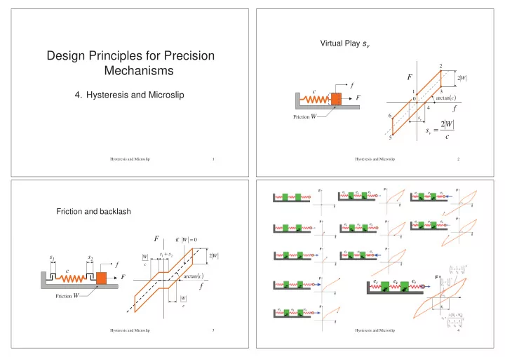
Virtual Play s v Design Principles for Precision 2 Mechanisms F 2 W f c 1 3 4. Hysteresis and Microslip ( ) F arctan c L 0 f 4 Friction W 6 s v 2 W s v = c 5 Hysteresis and Microslip 1 Hysteresis and Microslip 2
Virtual Play s v Design Principles for Precision 2 Mechanisms F 2 W f c 1 3 4. Hysteresis and Microslip ( ) F arctan c L 0 f 4 Friction W 6 s v 2 W s v = c 5 Hysteresis and Microslip 1 Hysteresis and Microslip 2 Friction and backlash F if W = 0 s + s 2 s 1 s 2 W W 1 2 f c c ( ) arctan F c L f Friction W W c Hysteresis and Microslip 3 Hysteresis and Microslip 4
Hysteresis curve with distributed friction and compliance Friction is load dependent: the butterfly-tie 3 F 2 1 0 f equilibriu m in moving direction Moment equilibriu m : F c b F = cf + 2 µ N = N = F b f a 1 − 2 µ a F c 7 2 F = cf − µ N = b f 1 + 2 µ a Hysteresis and Microslip 5 Hysteresis and Microslip 6 Minimize virtual play Hysteresis in clamped joints lower friction - uniform clamping pressure: σ σ v σ σ - friction coefficient: µ µ µ µ - clamps are infinitely stiff higher stiffness - force transfer under slip Hysteresis and Microslip 7 Hysteresis and Microslip 8
Hysteresis in clamped joints Alternating load in clamped joints Fs u clamp = 2 EA EA c clamp = 2 s EA c beam = l F Fs 2 ⋅ s ⋅ b ⋅ µ ⋅ σ = F → s = Fs u beam = v s v = 2 ⋅ b ⋅ µ ⋅ σ EA v 2 EA cross-section A Hysteresis and Microslip 9 Hysteresis and Microslip 10 Minimising virtual play Hysteresis-free clamping A E p c A ⋅ E = A ⋅ E → = p p c c A E c p Fs s = ( A = bt ) v 2 EA 2 F � Clamping of a tapered beam s = v 2 F 4 σ µ Eb t is not very practical, maybe gluing is… v F s = 2 ⋅ b ⋅ µ ⋅ σ v Hysteresis and Microslip 11 Hysteresis and Microslip 12
Hysteresis-loops, summary Transfer of torques analogies tension glue tension glue seam seam Hysteresis and Microslip 13 Hysteresis and Microslip 14 Inaccurate z-positioning while clamping hubs (1/2) Clamping a bush might cause axial displacement Hysteresis and Microslip 15 Hysteresis and Microslip 16
Inaccurate z-positioning while clamping hubs (2/2) Clamping optical system of radial follower CD system No axial slip if: L > 4 ⋅ D ( ν = 0 . 3 and µ ≈ ν ) Hysteresis and Microslip 17 Hysteresis and Microslip 18 Hysteresis in structures Hysteresis in bolted connections (1/2) preferebly high surface pressures Hysteresis and Microslip 19 Hysteresis and Microslip 20
A “bed of nails” for free-of-hysteresis clamping Hysteresis in bolted connections (1/2) Hysteresis and Microslip 21 Hysteresis and Microslip 22 Clamping a plate spring Stopping by means of clamping 2 Ebt c finger = 2 y F Width: b Hysteresis and Microslip 23 Hysteresis and Microslip 24
Rotation of the cork eleviates the friction Alleviating friction by means of slip in a different direction D d � ϕ v v v l 1 F F , � v t = ϕ ⋅ d w l w 2 F w Hysteresis and Microslip 25 Hysteresis and Microslip 26 Self-locking Self-aligning gear wheel self - locking if : l h G < 2 µ G h h < 2 µ l G F w = G 2 F w = µ ⋅ Gl h α The locking can be alleviated when rotating the shaft: sin α = h 2 l ⋅ µ Hysteresis and Microslip 27 Hysteresis and Microslip 28
Self locking Rapid and accurate tape feed mechanism F F ⋅ sin α W N F α α α α self - locking if : α < µ Hysteresis and Microslip 29 Hysteresis and Microslip 30 Positioning against pins virtual play self-locking ( ) 2 W + W α 1 2 s v = The principle of self-positioning c s v c N ? µ µ W ? W ? 1 2 Hysteresis and Microslip 31 Hysteresis and Microslip 32
(1) determine the poles and nesting torque direction (1) determine the poles and nesting torque direction M = F ⋅ ε n ε F P 2,3 n F n n 2 n 3 n 2 n 3 P 1,2 P 1,3 P 1,2 P 1,2 1 n 1 n 1 1 1 2 3 2 3 2 3 Assumption: no friction in contacts! Hysteresis and Microslip 33 Hysteresis and Microslip 34 (1) determine the poles and nesting torque direction (2) determine the prohibited zones F n n 2 n 3 n 2 n 3 P 1,2 P 1,2 n 1 n 1 F 1 1 n 2 3 2 3 Hysteresis and Microslip 35 Hysteresis and Microslip 36
Alternative: find F n on basis of equal pin reaction (2) determine the prohibited zones F F R F n P 2,3 n n 2 n 3 n 2 F c 1 1 R n 3 P 1,2 P 1,3 1 F c F c F n n 1 n 1 1 1 R 2 3 2 3 R 3 2 2 3 2 3 Hysteresis and Microslip 37 Hysteresis and Microslip 38 (1) Or find M n on basis of equal pin reaction M n Now friction comes into play…… Hysteresis and Microslip 39 Hysteresis and Microslip 40
µ ε r 2 F n F n 2 n n 2 F F P 2,3 P 1,2 P 2,3 n n n 1 n 1 1 1 n 2 F F r 1 P 1,2 w , 1 w , 2 2 3 2 3 n 3 P 1,3 P 1,3 P 1,2 P 1,2 n 1 1 1 2 3 2 3 Hysteresis and Microslip 41 Hysteresis and Microslip 42 D L y R l L M L − l x P f l 3 A ϕ B C l ∆ F R M L − l Shortening ideal rotation L Hysteresis and Microslip 43 Hysteresis and Microslip 44
Well-defined line of action of the nesting force F n O F B n A M Hysteresis and Microslip 45
Recommend


More recommend
Explore More Topics
Stay informed with curated content and fresh updates.