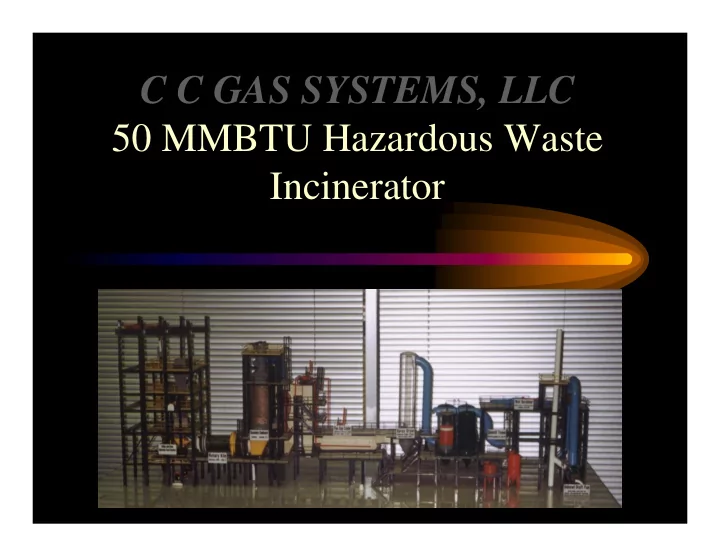

C C GAS SYSTEMS, LLC 50 MMBTU Hazardous Waste Incinerator
GENERAL OVERVIEW The plant consists of the following items supplied by ,C C GAS SYSTEMS, LLC • • Tank farm consisting of five (5) each high BTU storage tanks c/w steam coils and five (5) each low BTU storage tanks w/o steam coils. In addition to the above tanks, future expansion has been allowed for four (4) more tanks, two (2) high BTU and two (2) low BTU tanks. • Each tank is blanketed with 45 psig of nitrogen, and connected to a scrubber system consisting of a condenser to collect the gases as a liquid and return them to the feed stream and a charcoal absorber to scrub the gases prior to releasing them to the atmosphere. • Incinerator train consisting of the following, feed system, rotary kiln & afterburner, flue gas cooler, spray dryer, baghouses, quench tower, cyclone separator, I.D. fan, exhaust stack and control unit. • Additional appurtenances will be required to make the plant a complete operating facility. • Optional equipment to utilize the steam from the flue gas cooler can be purchased at additional cost! (i.e.: desalination plant)
Tank Farm FUTURE EXISTING LOW BTU WASTE NITROGEN 45 PSIG HIGH BTU WASTE c/w STEAM COILS TO ATMOSPERE CONDENSER CHARCOL ABSORBER PUMPS : • Loading and Unloading • Transfer
Feed System LUGGER BUCKET DUST SUPPRESSION SPRAY BULK RECEIVING HOPPER SEAL GATE VALVE DRUM RAM FEED NITROGEN PURGE SHREDDER SOLID FEED HOPPER CARBON DIOXIDE PURGE DOUBLE AIR LOCK VALVES SCREW FEED AUGAR
ROTARY KILN & AFTERBURNER Relief Vent To Flue Gas Cooler Stationary Second Stage 1900 to 2400 F (Residence time 2 sec. min.) Rotary Kiln (First Stage) FEED TO ROTARY KILN 900 to 1800 F FROM BULK FEED SYSTEM (-1/4" to -1/2" W .C.) Transition Section (Residence time 27.3 to 273 min.) & (1.3% slope) Ash Hopper (0.2 to 2.0 RPM) High and Low BTU Liquid W aste from Storage & Natural Gas for Pilot/Burner
FLUE GAS COOLER H 2 O W Q U E N C H O E R T CONVECTION SECTION 3 DRUM UNIT R A D E N T S E C T O N I I FROM AFTERBURNER TO SPRAY DRYER STEAM DRUM
FR O M C O N V E C T IO N SE C TIO N C A U ST IC S O D A SPRAY DRYER C ollector S p ra y 6 50 to 3 50 F Dryer A sh & TO B A G H O U SE (S )
FROM SPRAY DRYER House Bag BAGHOUSE(S) House Bag House Bag House Bag HCL & S02 Monitor TO QUENCH TOWER
QUENCH TOWER, CYCLONE SEPARATOR, I.D. FAN, and EXHAUST STACK CAUSTIC SODA Wet ID Scrubber Quench Fan Tower (Free Jet) 350 to 160 F (Cyclonic E Separator) x h a u s t
CONTROL ROOM
MCC CONTROL PANEL
DESALINATON
WASTE STREAMS The plant was designed to handle five (5) categories of waste streams: • High BTU Liquids (LHV = 18,400 BTU/LB) • Low BTU Liquids (SP.GR. of .69 to 1.36) • Solids (Dirt and Rock) 100 to 120 LB/Cu. Ft. • Reactive Wastes • Drum Wastes
WASTE STREAMS NOT ACCEPTABLE • Volatile metals • Radioactive materials • Explosive materials • Significant arsenic containing compounds • PCB’s and Dioxins (w/o modifications) • Waste Containing Chlorine in excess of 10.6% wt. (w/o modifications) • Municipal Waste (Capable, not efficient) • Infectious Waste • Asbestos Materials
UTILITIES NOT PROVIDED • Electricity • Water (Potable) • Compressed Air • Natural Gas • Boiler Feed Water • Nitrogen (N 2 ) • Carbon Dioxide (CO 2 ) • Caustic Soda (NaOH) (50% solution with H 2 O) • Water Disposal
BEST AVAILABLE EMISSION CONTROL TECHNOLOGY (BACT) BACT for this plant is: • At least 99% of the chlorine in the feed will be removed from the flue gas. • More than 95% of the sulfur dioxide in the flue gas will be removed. • Particulate matter will be reduced to 0.02 grains/dscf of the flue gas corrected to 7% oxygen. • Nitrogen oxide emissions will average less than 0.3 LBS/Million BTU heat input.
GENERAL COMMENT • The original design specified a 99.99 (minimum) destruction of the hydrocarbons in the waste feed. • The Flue Gas Cooler produces steam at a rate of 34,000 lbs./hr., 460 PSIG, and 650 F. The most efficient use of this steam would be a desalination plant, which should produce around one (1) MMGPD of potable water.
Recommend
More recommend