Beam Transfer Devices: Septa & Kickers M.J. Barnes CERN - - PDF document

beam transfer devices septa kickers
SMART_READER_LITE
LIVE PREVIEW

Beam Transfer Devices: Septa & Kickers M.J. Barnes CERN - - PDF document

Beam Transfer Devices: Septa & Kickers M.J. Barnes CERN TE/ABT Acknowledgements: J. Borburgh, M. Hourican, T. Masson, J-M Cravero, L. Ducimetire, T. Fowler, V. Senaj, L. Sermeus, B. Goddard, M. Gyr, J. Uythoven 06/11/2013 CAS: Septa


slide-1
SLIDE 1

1

06/11/2013

CAS: Septa & Kickers. M.J. Barnes.

1

Beam Transfer Devices: Septa & Kickers

M.J. Barnes CERN TE/ABT

Acknowledgements:

  • J. Borburgh, M. Hourican, T. Masson, J-M Cravero,
  • L. Ducimetière, T. Fowler, V. Senaj, L. Sermeus,
  • B. Goddard, M. Gyr, J. Uythoven

06/11/2013

CAS: Septa & Kickers. M.J. Barnes.

2

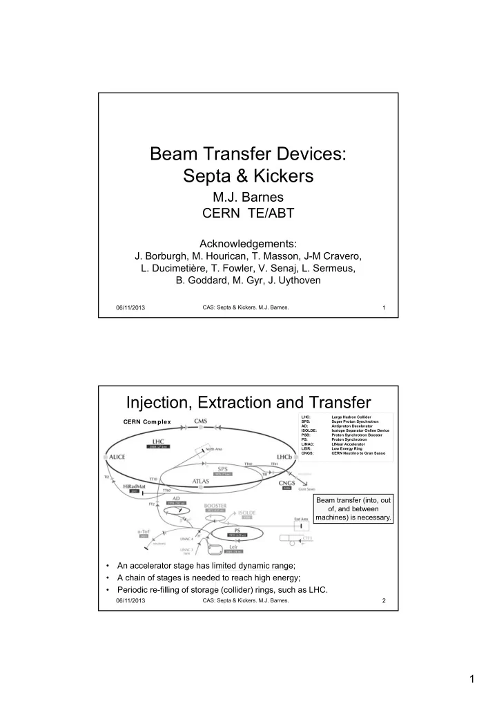
Injection, Extraction and Transfer

  • An accelerator stage has limited dynamic range;
  • A chain of stages is needed to reach high energy;
  • Periodic re-filling of storage (collider) rings, such as LHC.

CERN Com plex

LHC: Large Hadron Collider SPS: Super Proton Synchrotron AD: Antiproton Decelerator ISOLDE: Isotope Separator Online Device PSB: Proton Synchrotron Booster PS: Proton Synchrotron LINAC: LINear Accelerator LEIR: Low Energy Ring CNGS: CERN Neutrino to Gran Sasso

Beam transfer (into, out

  • f, and between

machines) is necessary.

slide-2
SLIDE 2

2

06/11/2013

CAS: Septa & Kickers. M.J. Barnes.

3

Beam Transfer

  • Beam transfer into and out of rings is required;
  • A combination of septa and kickers are

frequently used – both are needed;

  • Septa have two vacuum chambers. Kickers have

a single vacuum chamber;

  • Septa can be electrostatic or magnetic;
  • Magnetic septa provide slower field rise/fall

times (possibly DC), but stronger field, than kicker magnets;

  • Kicker magnets provide fast field rise/fall times,

but relatively weak fields.

06/11/2013

CAS: Septa & Kickers. M.J. Barnes.

4 Kicker Location Beam momentum (GeV/c) # Magnets Gap Height [Vap] (mm) Current (kA) Impedance (Ω) Rise Time (ns) Total Deflection (mrad) CTF3 0.2 4 40 0.056 50 ~4 1.2 PS Inj. 2.14 4 53 1.52 26.3 42 4.2 SPS Inj. 13/26 16 54 to 61 1.47/1.96 16.67/12.5 115/200 3.92 SPS Ext. (MKE4) 450 5 32 to 35 2.56 10 1100 0.48 LHC Inj. 450 4 54 5.12 5 900 0.82 LHC Abort 450 to 7000 15 73 1.3 to 18.5 1.5 (not T-line) 2700 0.275

Septum Location Beam momentum (GeV/c) Gap Height (mm)

  • Max. Current

(kA) Magnetic Flux Density (T) Deflection (mrad)

LEIR/AD/CTF (13 systems) Various 25 to 55 1 DC to 40 pulsed 0.5 to 1.6 up to 130 PS Booster (6 systems) 1.4 25 to 50 28 pulsed 0.1 to 0.6 up to 80 PS complex (8 systems) 26 20 to 40 2.5 DC to 33 pulsed 0.2 to 1.2 up to 55 SPS Ext. 450 20 24 1.5 2.25

Example Parameters for Septa and Kickers in the CERN Complex

slide-3
SLIDE 3

3

06/11/2013

CAS: Septa & Kickers. M.J. Barnes.

5

Lorentz Force

The Lorentz force is the force on a point charge due to electromagnetic fields. It is given by the following equation in terms of the electric and magnetic fields:

  • F is the force (in Newton) – vector quantity;
  • E is the electric field (in volts per meter) – vector quantity;
  • B is the magnetic field (in Tesla) – vector quantity;
  • q is the electric charge of the particle (in Coulomb)
  • v is the instantaneous velocity of the particle (in meters per second) –

vector quantity;

  • X is the vector cross product

06/11/2013

CAS: Septa & Kickers. M.J. Barnes.

6

Ref: http://hyperphysics.phy-astr.gsu.edu/hbase/magnetic/magfor.html

Right-Hand Rule Charge moving into plane of paper

(To right) (To left)

  • q

+q

B

q=0

North Pole of Magnet South Pole of Magnet

q` q`

Example of Deflection by Force in a Magnetic Field

slide-4
SLIDE 4

4

06/11/2013

CAS: Septa & Kickers. M.J. Barnes.

7

Beam Deflection due to a Magnetic Field

Where:

  • B is magnetic flux density (T);
  • p is beam momentum (GeV/c);
  • is the effective length of the magnet (usually different from the

mechanical length, due to fringe fields at the end of the magnet);

  • is the deflection angle due to the magnetic field (rads).

06/11/2013

CAS: Septa & Kickers. M.J. Barnes.

8

Example of Deflection by Force in an Electric Field

+

  • Opposites Attract !
  • q

+q

E

q=0

Negative Positive Charge moving into plane of paper

(Down) (Up)

slide-5
SLIDE 5

5

06/11/2013

CAS: Septa & Kickers. M.J. Barnes.

9

Beam Deflection due to an Electric Field

Where:

  • E is electric field (V/m);
  • p is beam momentum (GeV/c);
  • β is a unit-less quantity that specifies the fraction of the speed of light at

which the particles travel;

  • is the effective length of the magnet (usually different from the

mechanical length, due to fringe fields at the end of the magnet);

  • V is voltage (V);
  • d is gap (m);
  • is the deflection angle due to the electric field (rads).

Usually fixed by beam considerations 06/11/2013

CAS: Septa & Kickers. M.J. Barnes.

10

In general: a septum (plural septa) is a partition that separates two cavities or spaces. In a particle-accelerator a septum is a device which separates two field regions:

Region A Field free region (EA=0 & BA=0) Region B Region with homogeneous field (EB≠0 orBB ≠0) Septum

Important features of septa are a homogeneous field in one region, for deflecting beam, and a low fringe field next to the magnet so as not to affect the circulating beam.

slide-6
SLIDE 6

6

06/11/2013

CAS: Septa & Kickers. M.J. Barnes.

11

Single-Turn Injection – horizontal plane

  • Septum deflects the beam onto the closed orbit at the centre of the kicker;
  • Kicker (installed in circulating beam) compensates for the remaining angle;
  • Septum and kicker either side of quad to minimise kicker strength.

Septum magnet Kicker magnet (Installed in circulating beam) F-quad (horizontal plane)

t kicker field intensity injected beam

‘boxcar’ stacking

Circulating beam D-quad (horizontal plane)

Circulating beam

Field “free” region

Thin septum blade

Homogeneous field in septum

“n” 06/11/2013

CAS: Septa & Kickers. M.J. Barnes.

12

Fast Extraction uses a Kicker and a Septum

  • Kicker (installed in circulating beam) provides a deflection (typically a few mrad)

to extract beam;

  • Septum provides relatively strong field to further deflect extracted beam;
  • Septum “leak field” must not deflect circulating beam.

A septum is frequently used as a beam “Extractor/Injector” in conjunction with a “kicker” upstream/downstream.

Extracted Beam

Kicker Septum Field Field “free” region

Thin Septum Blade

Circulating Beam (not kicked) Kicked Beam (Installed in circulating beam)

slide-7
SLIDE 7

7

06/11/2013

CAS: Septa & Kickers. M.J. Barnes.

13

Septa

  • Main Types:

– Electrostatic Septum (DC); – DC Magnetic Septum; – Direct Drive Pulsed Magnetic Septum; – Eddy Current Septum; – Lambertson Septum (deflection orthogonal to kicker deflection).

  • Main Difficulties:

– associated with Electrostatic septa is surface conditioning for High Voltage; – associated with Magnetic septa are not electrical but rather mechanical (cooling, support of this septum blades, radiation resistance). The goal is to construct a magnet with a septum conductor as thin as possible, to “ease” the task of elements such as kickers.

06/11/2013

CAS: Septa & Kickers. M.J. Barnes.

14

“C” Magnet  Septum Magnet B

Current Density Is very high in Septum Blade I

slide-8
SLIDE 8

8

06/11/2013

CAS: Septa & Kickers. M.J. Barnes.

15

Extraction

  • Different extraction techniques exist, depending on requirements:

– Slow extraction of beam:

  • Experimental facilities generally use slow extracted beam. An optimum

slow extracted beam has a smooth, uniform spill.

– Fast, single-turn, extraction of beam:

  • Fast, single-turn, extraction is used in the transfer of beam from one

acceleration stage to another.

  • Usually higher energy than injection  stronger elements (e.g. ∫B.dl):

– At high energies many kicker and septum modules may be required; – To reduce kicker and septum strength, beam can be moved near to septum by closed orbit bump (true of injection too).

06/11/2013

CAS: Septa & Kickers. M.J. Barnes.

16

Septum for Multi-Turn Extraction

EB≠0

Beam Septum Blade

EA=0

Septum blade must be very thin (e.g. <0.1mm) to limit magnitude of losses: hence an electrostatic septum is generally used.

Beam bumped to septum; part of beam ‘shaved’ off each turn:

slide-9
SLIDE 9

9

06/11/2013

CAS: Septa & Kickers. M.J. Barnes.

17

Extraction with an Electrostatic Septum (1)

To allow precise matching of the septum position with the circulation beam trajectory, the magnet is also often fitted with a displacement system, which allows parallel and angular movement with respect to the circulating beam. Thin septum foil gives small interaction with beam. Orbiting beam passes through hollow support of septum foil (field free region). Extracted beam passes just on the other side of the septum (high, homogeneous, field region). Electrostatic septa generally use vacuum as an insulator, between septum and electrode, and are therefore normally in a vacuum tank. x y z

E d V

Circulating Beam Extracted Beam Septum Foil Electrode Support

06/11/2013

CAS: Septa & Kickers. M.J. Barnes.

18

Extraction with an Electrostatic Septum (2)

Typical technical specifications:

  • Electrode length : 500 - 3000 mm;
  • Gap width (d) variable: 10 - 35 mm;
  • Septum thickness: <=0.1 mm;
  • Vacuum (10-9 to 10-12 mbar range);
  • Voltage: up to 300 kV;
  • Electric field strength: up to 10 MV/m;
  • Septum Molybdenum foil or Tungsten

wires;

  • Electrode made of anodised aluminium,

Stainless Steel or titanium for extremely low vacuum applications;

  • Bake-able up to 300 °C for vacuum in

10-12 mbar range;

  • Power supplied by Cockroft-Walton type

high voltage generator.

Beam Screen Electrode Foil Foil Tensioners Deflector

slide-10
SLIDE 10

10

06/11/2013

CAS: Septa & Kickers. M.J. Barnes.

19

Extraction with a DC Magnetic Septum (1)

Continuously powered with a (high) current. Usually constructed with a multi-turn (series) coil, so as to reduce the current needed. The coil and the magnet yoke can be split in two, an upper and a lower part, to allow the magnet to be 'clamped' over the vacuum chamber of the extraction line. Rarely under vacuum. Upper half magnet yoke x y z Rear Conductor Septum Transport line vacuum chamber Lower half magnet yoke Circulating beam vacuum chamber

06/11/2013

CAS: Septa & Kickers. M.J. Barnes.

20

Extraction with a DC Magnetic Septum (2)

Typical technical specifications:

  • Magnetic length per magnet yoke: 400 -

1200 mm;

  • Gap height: 25 - 60 mm;
  • Septum thickness: 6 - 20 mm;
  • Outside vacuum;
  • Laminated steel yoke;
  • Multi turn coil, with water cooling circuits

(12 - 60 l/min.);

  • Current range: 1 - 10 kA;
  • Power supplied by controllable rectifier;
  • Power consumption: 10 - 100 kW !.

Cooling Electrical Connections Circulating Beam

slide-11
SLIDE 11

11

06/11/2013

CAS: Septa & Kickers. M.J. Barnes.

21

Direct Drive Pulsed Magnetic Septum (1)

Powered with a half sine wave current with a half period time of typically 3 ms. Coil is generally constructed as a single turn, so as to minimize magnet self-inductance. A transformer is used between power supply and magnet to allow use of standard 2kV capacitors. To allow precise matching of the septum position with the circulation beam trajectory, the magnet is also often fitted with a remote displacement system. Often under vacuum to minimize distance between circulating and extracted beam. Circulating Beam x y z Yoke Rear Conductor Septum Conductor Extracted Beam

B x x

06/11/2013

CAS: Septa & Kickers. M.J. Barnes.

22

Direct Drive Pulsed Magnetic Septum (2)

Typical technical specifications:

  • Magnetic length per magnet yoke: 300 -

1200 mm;

  • Gap height: 18 - 60 mm;
  • Septum thickness: 3 - 20 mm;
  • Vacuum (~10-9 mbar);
  • Laminated steel yoke of 0.35 mm - 1.5

mm thick laminations;

  • Single turn coil, with water cooling

circuits (1 - 80 l/min.);

  • Bake-able up to 200 °C;
  • Current: half-sine 7 - 40 kA, half-period

~3 ms;

  • Power supplied by capacitor discharge;

flat top of the current improved with 3rd harmonic circuit and active filters – (rectifier circuit used for up to 6s “pulse”);

  • A transformer is used between power

supply and magnet.

Remote positioning system Beam “monitor” Beam screen Infrared bake-out lamp Septum

slide-12
SLIDE 12

12

06/11/2013

CAS: Septa & Kickers. M.J. Barnes.

23

Eddy Current Magnetic Septum (1)

Powered with a half or full sine wave current with a period of typically 50 μs. Coil is generally constructed as a single turn, so as to minimize magnet self-inductance. The coil sits around the back leg of the C shaped yoke, and therefore coil dimensions are generally not critical. When the magnet is pulsed, the magnetic field induces eddy currents in the septum blade, counteracting the fringe field created. The septum can be made very thin, but water circuits may be needed at the edges to cool the septum. The field in the gap as function of time follows the coil current. The electrical resistance of the septum is kept low: once the septum current is flowing, it takes quite some time to decay away. x y z

  • I

I Gap C-shaped Yoke Coil Eddy Current Septum Blade Orbiting Beam

06/11/2013

CAS: Septa & Kickers. M.J. Barnes.

24

Eddy Current Magnetic Septum (2)

To reduce further the fringe field of the eddy current septum a copper box (return box) can be placed around the septum magnet. Also a magnetic screen can be added next to the septum conductor. These modifications permit the fringe field to be reduced to below 1/1000 of the gap field at all times and places. x y z

  • I

I Magnetic Screen Return Box Beam Screen Coil C-shaped Yoke

slide-13
SLIDE 13

13

06/11/2013

CAS: Septa & Kickers. M.J. Barnes.

25

Typical technical specifications:

  • Magnetic length per magnet yoke: 400 -

800 mm;

  • Gap height: 10 - 30 mm;
  • Septum thickness: 1 - 3 mm;
  • Vacuum (~10-9 mbar), or out of vacuum;
  • Steel yoke with 0.1 - 0.35 mm thick

laminations;

  • Single turn coil, with water cooling

circuits (1 - 10 l/min.);

  • Current: ~10 kA;
  • Fast pulsed : 50 μs;
  • Powered with a capacitor discharge;

half-sine or full sine-wave.

Eddy Current Magnetic Septum (3)

BS1 Prototype Eddy Current Septum

Septum Blade 06/11/2013

CAS: Septa & Kickers. M.J. Barnes.

26

Lambertson Septum (principle)

  • Current: DC or pulsed;
  • Conductors are enclosed in steel

yoke, “well away” from beam;

  • Thin steel yoke between Aperture

and circulating beam – however extra steel required to avoid saturation;

  • Septum, as shown, difficult to

align.

  • Extraction Septum shown:
  • Use kicker to deflect beam

horizontally into aperture;

  • Lambertson deflects beam

vertically (orthogonal to kicker deflection). x I

I

  • Circulating

Beam Steel yoke Coil Steel to avoid saturation Aperture Thin Septum

slide-14
SLIDE 14

14

06/11/2013

CAS: Septa & Kickers. M.J. Barnes.

27

LHC Injection – Lambertson Septum

  • 1. Septum deflects beam horizontally to

the right;

  • 2. Kicker deflects beam vertically onto

central orbit.

  • 3. Note: To minimize field in LHC beam-

pipes, additional screen is used.

Transfer line from SPS Counter-rotating LHC Beam Beam Injected into LHC 06/11/2013

CAS: Septa & Kickers. M.J. Barnes.

28

Powering Pulsed Septa

Third Harmonic Circuit: A third harmonic circuit is used to obtain a better flattop current than a basic sinusoidal discharge current:

  • The capacitors are accurately charged to the required voltage;
  • The third harmonic circuit generates a current which is superimposed upon

(adds to) the discharge current of the fundamental current.

  • A transformer is used to allow the use of standard 2kV capacitors on the primary

and to give the required high current on the secondary.

  • An active filter circuit (not shown) can be used to obtain a stability of flattop current
  • f 10-4 over a time of 500μs.

flattop

slide-15
SLIDE 15

15

06/11/2013

CAS: Septa & Kickers. M.J. Barnes.

29

Bibliography for Septa

  • M.J. Barnes, J. Borburgh, B. Goddard, M. Hourican, “Injection and Extraction

Magnets: Septa”, CERN Accelerator School CAS 2009: Specialised Course on Magnets, Bruges, 16-25 June 2009, arXiv:1103.1062 [physics.acc-ph].

  • J. Borburgh, M. Crescenti, M. Hourican, T. Masson, “Design and Construction of the

LEIR Extraction Septum”, IEEE Trans. on Applied Superconductivity, Vol. 16, No. 2, June 2006, pp289-292.

  • M.J. Barnes, B. Balhan, J. Borburgh, T. Fowler, B. Goddard, W.J.M. Weterings, A.

Ueda, “Development of an Eddy Current Septum for LINAC4”, EPAC 2008.

  • J. Borburgh, B. Balhan, T. Fowler, M. Hourican, W.J.M. Weterings, “Septa and

Distributor Developments for H- Injection into the Booster from Linac4”, EPAC 2008.

  • S.Bidon, D.Gerard, R.Guinand, M.Gyr, M.Sassowsky, E.Weisse, W.Weterings,

A.Abramov, A.Ivanenko, E.Kolatcheva, O.Lapyguina, E.Ludmirsky, N.Mishina, P.Podlesny, A.Riabov, N.Tyurin, “Steel Septum Magnets for the LHC Beam Injection and Extraction”, Proc. of EPAC 2002, Paris.

  • J.M. Cravero & J.P. Royer, “The New Pulsed Power Converter for the Septum

Magnet in the PS Straight Section 42”, CERN PS/PO/ Note 97-03, 1997.

  • J.P. Royer, “High Current with Precision Flat-Top Capacitor Discharge Power

Converters for Pulsed Septum Magnets”, CERN/PS 95-13 (PO), 1995.

  • http://psdata.web.cern.ch/psdata/www/septa/xseh.htm.

06/11/2013

CAS: Septa & Kickers. M.J. Barnes.

30

Kickers

slide-16
SLIDE 16

16

06/11/2013

CAS: Septa & Kickers. M.J. Barnes.

31

Fast Single-Turn Extraction – same plane

  • Kicker deflects the entire beam into the septum in a single turn (time

selection [separation] of beam to be extracted);

  • Septum deflects the beam entire into the transfer line (space separation of

circulating and extracted beam). Whole beam kicked into septum gap and extracted. Septum magnet Closed orbit bumpers Kicker magnet (Installed in circulating beam) Homogeneous field in septum

06/11/2013

CAS: Septa & Kickers. M.J. Barnes.

32

Fast Single Turn Injection/Extraction

  • Kickers are used for transfer of beams between accelerators and for dumping beam.
  • Septum deflection may be in the other plane to the kicker deflection.
  • The kicker magnetic field must rise/fall within the time period between the beam

bunches, without deviating from the flat top and bottom of the pulse – Typical field rise/fall times range from tens to hundreds of nanoseconds and pulse width ranging from tens of nanoseconds to tens of microseconds;

  • If a kicker exhibits a time-varying structure in the pulse shape this can translate into

small offsets with respect to the closed orbit (betatron oscillations).

  • A fast (pulse forming) circuit is required !

Particles in SPS extraction kicker rise- and fall-time gaps

slide-17
SLIDE 17

17

06/11/2013

CAS: Septa & Kickers. M.J. Barnes.

33

Characteristic Impedance of Coaxial Cable

Where: a is the outer diameter of the inner conductor (m); b is the inner diameter of the outer conductor (m); is the permittivity of free space (8.854x10⁻¹² F/m). Cross-section of coaxial cable Dielectric (permittivity εr) Capacitance per metre length (F/m): Inductance per metre length (H/m): Characteristic Impedance (Ω): (typically 20 Ω to 50 Ω). Delay per metre length: (~5ns/m for suitable coax cable).

06/11/2013

CAS: Septa & Kickers. M.J. Barnes.

34

Pulse Forming Circuit: General Case

  • At t=0, when the ideal switch closes, the load

potential (VL) is given by: A voltage pulse of “(α-1)V” propagates from the load end of the line towards the charging end.

  • At the charging end the reflection coefficient ( ) is

+1 and hence “(α-1)V” is reflected back towards the load end of the line.

  • At the load end of the line:

say. and hence “β(α-1)V” is reflected back towards the charging end of the line.

  • Etc.

Time Impedances need to be matched to avoid reflections !, (i.e. β=0  ZL=Z0) Charging end of line Load end

  • f line
slide-18
SLIDE 18

18

06/11/2013

CAS: Septa & Kickers. M.J. Barnes.

35

Pulse Forming Circuit: Matched Load (ZL=Z0)

  • At t=0, when the ideal switch closes, the load

potential (VL) is given by (Note: ZL=Z0): A voltage pulse of −V/2 propagates from the load end of the line towards the charging end.

  • At the charging end the “reflection coefficient”

(Γ) is +1 and hence the −V/2 is reflected back towards the load end of the line.

  • At the load end of the line:

and hence no voltage is reflected back towards the charging end of the line.

Note: PFN voltage is twice the load voltage. Charging end of line Load end

  • f line

propagates towards charging end propagates toward load end after reflection

switch closes

propagates toward load end. Load voltage falls to zero at

06/11/2013

CAS: Septa & Kickers. M.J. Barnes.

36

Simplified Schematic of Kicker System

Typical circuit operation:

  • PFN/PFL is charged to a voltage Vp by the RCPS;
  • Main Switch closes and a pulse of magnitude (Vp/2) is launched, through the

transmission line, towards the magnet.

  • Once the current pulse reaches the (matched) terminating resistor full-field has

been established in the kicker magnet;

  • The length of the pulse in the magnet can be controlled in length, between 0 and

2τp, by adjusting the timing of the Dump Switch relative to the Main Switch.

  • Note: the Dump Switch may be an inverse diode: the diode will “automatically”

conduct if the PFN voltage reverses, but there is no control over pulse-length.

  • Typically matched impedances;
  • PFL = Pulse Forming Line

(coaxial cable);

  • PFN = Pulse Forming Network

(lumped elements);

  • RCPS = Resonant Charging

Power Supply;

  • Floating switch.
slide-19
SLIDE 19

19

06/11/2013

CAS: Septa & Kickers. M.J. Barnes.

37

Where:

  • p is beam momentum (GeV/c);
  • β is a unit-less quantity that specifies the fraction of the speed of light at

which the particles travel;

  • is the effective length of the magnet (usually different from the

mechanical length, due to fringe fields at the end of the magnet).

Angular Deflection Due To Magnetic and Electric Fields

Ferrite Return

+HV

x

  • By

Fx x y z

Key: Proton beam moving out of plane of paper; Current flow into plane of paper; Current flow out of plane of paper;

x

  • 06/11/2013

CAS: Septa & Kickers. M.J. Barnes.

38

Where:

  • is permeability of free space (4πx10-7 H/m);
  • N

is the number of turns;

  • I

is current (A);

  • is the distance between the inner edges of the HV and return conductors (m);
  • is the distance between the inner “legs” of the ferrite (m);
  • is inductance per metre length of the kicker magnet (H/m).

Usually 1 for a kicker magnet Minimum value set by beam parameters

Hence: “I” determines By

Minimum value set by beam parameters

Electrical Parameters for a Magnetic Kicker

Ferrite Return

+HV

x

  • By

Hap Vap

I I

slide-20
SLIDE 20

20

06/11/2013

CAS: Septa & Kickers. M.J. Barnes.

39

Kicker Magnets

In general kicker magnets have to be fast and therefore usually only have a single turn: multi-turns are

  • nly used for, slower, lumped

inductance kicker magnets.

Design options for kicker magnets:

  • 1. Type: “lumped inductance” or “transmission line” (with

specific Z) ?;

  • 2. Machine vacuum: install in or external to machine vacuum?;
  • 3. Aperture: window frame, closed C-core or open C-core ?;
  • 4. Termination: matched impedance or short-circuited ?.

06/11/2013

CAS: Septa & Kickers. M.J. Barnes.

40

Lumped Inductance Kicker Magnets

Although a lumped-type magnet has a simple structure, in most cases it cannot be applied to a fast kicker system because of its impedance mismatch and its slow

  • response. The lumped inductance kicker is generally useable only when a rise time

above a few hundreds of ns is required. The termination is generally either in series with the magnet input or else the magnet is short-circuit. In both cases the magnet only sees (bipolar) voltage during pulse rise & fall. With a short-circuit termination, magnet current is doubled.

A capacitor can be added to a lumped inductance magnet, but this can provoke some overshoot:

Magnet current rise for a step input voltage:

0100 199 298 397 496 595 694 793 892 991 1090

Requires several time-constants (Z) (Z)

slide-21
SLIDE 21

21

06/11/2013

CAS: Septa & Kickers. M.J. Barnes.

41

Transmission Line Kicker Magnet:

  • Ferrite C-cores are sandwiched between high

voltage (HV) capacitance plates;

  • One C-core, together with its ground and HV

capacitance plates, is termed a cell. Each cell conceptually begins and ends in the middle of the HV capacitance plates;

  • The “filling time” (τm) is the delay required for

the pulse to travel through the “n” magnet cells.

  • Developed at CERN in early 1960’s;
  • Consists of few to many “cells” to approximate a coaxial cable;

(#1) (#2) (#n) (#[n-1])

For a given cell length, Lc is fixed by aperture dimensions.

06/11/2013

CAS: Septa & Kickers. M.J. Barnes.

42

Transmission Line Kicker Magnet:

Transmission line kicker magnets have much faster field rise time than equivalent lumped

  • magnets. However, design and construction is more complicated and costly.

For a magnet terminated with a matched resistor: field rise time starts with the beginning of the voltage pulse at the entrance of the magnet and ends with the end of the same pulse at the output. Field rise is given by the sum of the voltage rise time and the magnet filling time : The field builds up until the end of the voltage rise at the output of the magnet. Hence it is important that the pulse does not degrade while travelling through the magnet. Thus the magnet cut-off frequency is a key parameter, especially with field rise times below ~100 ns. Cut-off frequency (fc) depends on series inductance (Ls) associated with the cell capacitor (Cc): Thus, Ls should be kept as low as possible and the cell size small. However cells cannot be to small (voltage breakdown & cost).

Flux

Vin V

  • ut
slide-22
SLIDE 22

22

06/11/2013

CAS: Septa & Kickers. M.J. Barnes.

43

Installing kicker magnets in machine vacuum:

Advantages:

  • Aperture dimensions are minimized;
  • Therefore voltage and current are minimized for a given

kick, rise-time and length (number of magnets is minimized);

  • Machine vacuum is a reliable dielectric (70kV/cm OK) –

generally “recovers” after a flashover, whereas a solid dielectric, outside vacuum, may not recover.

Disadvantages:

  • Costly to construct (bake-out,

vacuum tank, pumping);

  • Coupling impedance to beam

(a ceramic tube, suitably treated, may be required in any case).

Ferrite Return

+HV

x

  • By

Hap Vap

I I

06/11/2013

CAS: Septa & Kickers. M.J. Barnes.

44

Transmission Line Kicker Magnet

  • Transmission line magnets are usually installed in a vacuum chamber

to withstand high voltage between the capacitor plates;

  • In this case, a vacuum enclosure with expensive feedthroughs is

necessary;

  • Careful bake-out is required to control out-gassing from the ferrite core

and therefore beam loss. LHC Injection Kicker

  • 2.7m long magnet;
  • 33 cells;
  • Lc≃100nH, Cc ≃ 4nF

(per cell values);

  • Fill-time ≈ 680ns;
  • 5Ω characteristic

impedance.

slide-23
SLIDE 23

23

06/11/2013

CAS: Septa & Kickers. M.J. Barnes.

45

Kicker Magnet Magnetic Circuit

  • Normally a magnetic circuit is used which

contains magnetic material: without magnetic material the effective value of Vap is greatly increased, therefore requiring more current to achieve the required field. In addition, magnetic material improves field uniformity.

  • NiZn Ferrite is usually used, with μr≈1000:

– Field rise can track current rise to within ~1ns; – Has low remnant field; – Has low out-gassing rate, after bake-out.

  • Sometimes the return conductor is behind the

yoke (for beam gymnastic reasons) – this increases Lc by about 10%.

  • To reduce filling time by a factor of two FNAL

and KEK use a window frame topology:

– It can be considered as two symmetrical C- magnets energized independently. – Requires two generators to achieve the reduced filling time. – Conducting “shields” are used between the two ferrite C-cores to reduce beam coupling impedance.

Window Frame Magnet By Vap

Hap Ferrite Ferrite

x

  • I

Ferrite Return

x

By Hap

  • Vap

I I

C-core Magnet

06/11/2013

CAS: Septa & Kickers. M.J. Barnes.

46

Transmission Line Kicker Magnet Termination

When space is at a premium, a short circuit termination has the advantage of doubling kick (for a given system impedance): in addition, a short circuit termination reduces the time during which the magnet is exposed to high voltage. However disadvantages include:

  • fill-time of the kicker magnet is doubled;
  • magnet experiences voltage of both polarities;
  • if the dump-switch is used to control pulse length it must

be bi-directional (uni-directional is suitable if dump-switch is only acting as an inverse diode, i.e. not controlling pulse length);

  • beam can be affected (resonances, below magnet cut-
  • ff frequency, with kicker circuitry).
slide-24
SLIDE 24

24

06/11/2013

CAS: Septa & Kickers. M.J. Barnes.

47

Beam Coupling Impedance

In order to reduce beam coupling impedance the ferrite must be shielded from the beam, by providing a path for beam image current. However the design must ensure that eddy-currents, induced by the fast rising field, do not unduly increase field rise-time. LHC Injection Kicker: ceramic tube with “beam-screen” conductors in slots MKE Kicker: serigraphy

  • n ferrite

Ferrite HV Plate

06/11/2013

CAS: Septa & Kickers. M.J. Barnes.

48

Pulse Forming Line (PFL)

PFL (cable) becomes costly, bulky and the droop becomes significant (e.g. ~1%) for pulses exceeding about 3μs width.

Reels of PFL

  • Simplest configuration is a PFL charged to twice the needed pulse voltage;
  • PFL (cable) give ripple free pulses, but low attenuation is essential (especially

with longer pulses) to keep droop and “cable tail” within specification;

  • Attenuation is adversely affected by the use of semiconductor layers to

improve voltage rating;

  • Hence, for PFL voltages above 50kV, SF6 pressurized PE tape cables are

used.

slide-25
SLIDE 25

25

06/11/2013

CAS: Septa & Kickers. M.J. Barnes.

49

Pulse Forming Network (PFN)

System Parameters:

  • Field flat top duration ≤ 7.86μs;
  • Field flat top ripple < ±0.5%;
  • Field rise-time 0.5% to 99.5% = 0.9μs;
  • Kick strength per magnet = 0.325 T·m;
  • Nominal PFN Voltage = 54kV;
  • Nominal Magnet Current = 5.4kA.

LHC Injection PFN:

  • 5Ω system (two parallel 10Ω “lines”);
  • Nominal PFN Voltage = 54kV;
  • Single continuous coil per 10Ω line,

4.356 m long, with 198 turns and a pitch of 22 mm;

  • The 26 central cells of the coils are not

adjustable and therefore defined with high precision.

  • Copper tube wound on a rigid fibreglass

coil former. Schematic for an LHC Injection PFN:

PFN Line #1 PFN Line #2 “Cell”

LHC Injection PFN

A PFN is an artificial coaxial cable made of lumped elements.

06/11/2013

CAS: Septa & Kickers. M.J. Barnes.

50

Thyratron Switches

In general deuterium thyratrons are used as the power switch. Three-gap thyratrons can hold-off 80kV and switch 6kA of current with a 30ns rise-time (10% to 90%) [~150kA/μs]. BUT: care must be taken, e.g. …..

– Coaxial housings for low inductance; – Adequate insulation to the housing; – Erratic turn-on (turn-on without a trigger being applied): reduced significantly by “fast” (~ms) charging of the PFN/PFL; – Appropriate thyratron for anticipated short-circuit and fault conditions.

~340mm

slide-26
SLIDE 26

26

06/11/2013

CAS: Septa & Kickers. M.J. Barnes.

51

Semiconductor Switches

In some applications thyratron switches cannot be used; e.g. for the dump (abort) kickers in the LHC where the generator voltage must track the beam energy. In this case high power semiconductor switches are used (when rise-time ≥ 1μs) – to avoid erratic turn-on

  • f a thyratron and to allow a wide dynamic range of operation.

Maintenance is significantly reduced with a semiconductor switch.

GTO die damaged during testing at high di/dt

LHC dump parameters:

  • Ten series GTO’s

(VDRM=4.5kV);

  • Voltage range: 2.2kV – 30kV

(450GeV to 7TeV);

  • Current range: 1.3kA – 18.5kA;
  • Magnet current flat top: 95μs;
  • Maximum di/dt: 32kA/μs (~1/5th
  • f a thyratron).

06/11/2013

CAS: Septa & Kickers. M.J. Barnes.

52

CTF3 Tail Clipper: Overview

The beam pulse extracted from the CR is 35 A and 140

  • ns. The tail-clipper must

have a fast field rise-time,

  • f 5 ns or less, to minimize

uncontrolled beam loss. The flatness of the kick pulse is not important as deflected beam is to be thrown away.

Beam Pulse Schematic of Tail-Clipper

Each (of 8) pulse generator is composed of a 50Ω (Z) PFL, a fast semiconductor (Behlke) switch, 50 Ω stripline plates (no magnetic material) and a matched terminating resistor.

PFL

slide-27
SLIDE 27

27

06/11/2013

CAS: Septa & Kickers. M.J. Barnes.

53

CTF3 Tail Clipper: Striplines

From CTF3 CR To CLEX

Beam (e-)

Strip-line at positive voltage Strip-line at negative voltage

Fe

Deflection due to Electric Field:

From CTF3 CR To CLEX

Beam (e-)

I I

Fm

B B B B B B

Deflection due to Magnetic Field:

Strip-lines fed

from CLEX end +V

  • V

295mm (x4) 1.52m

Ftotal = Fe + Fm, Note: Fe = Fm for the tail clipper.

06/11/2013

CAS: Septa & Kickers. M.J. Barnes.

54

CTF3 Tail-Clipper Hardware

Behlke Switch (8kV, 200A): Very Low Inductance Connections

10V Trigger from Gate Driver PCB PFN To Load Peaking Capacitor 9 Parallel 50Ω Outputs

Gate Driver PCB (9 Parallel 50Ω Outputs [to drive 8 Behlke Switches])

Input Trigger (5V) Note: Behlke switch contains series connected, fast turn-on, MOSFETs.

slide-28
SLIDE 28

28

06/11/2013

CAS: Septa & Kickers. M.J. Barnes.

55

Current in 50Ω load (2.5ns rise, 5.6kV PFN) 5V Trigger Pulse Output of Gate Driver (2.5ns rise 0.5V to 7.5V) 56A (53A [40A] reqd. for 3 [4] sets of striplines).

Field rise-time of ~4.0ns [~3.2ns] predicted using PSpice (with td of 1.27ns), 0.25% to 99.75%, with measured current waveform, for 56A.

  • Meas. Waveforms: Normal Op.

S/N 847409; 5x10pF

06/11/2013

CAS: Septa & Kickers. M.J. Barnes.

56

Bibliography for Kickers

  • M.J. Barnes, L. Ducimetiére, T. Fowler, V. Senaj, L. Sermeus, “Injection and extraction magnets:

kicker magnets”, CERN Accelerator School CAS 2009: Specialised Course on Magnets, Bruges, 16-25 June 2009, arXiv:1103.1583 [physics.acc-ph].

  • D. Fiander, K.D. Metzmacher, P.D. Pearce, “Kickers and Septa at the PS complex, CERN”,

Prepared for KAON PDS Magnet Design Workshop, Vancouver, Canada, 3-5 Oct 1988, pp71-79.

  • M.J. Barnes, G.D. Wait, I.M. Wilson, “Comparison of Field Quality in Lumped Inductance versus

Transmission Line Kicker Magnets”, EPAC 1994, pp2547-2549.

  • G. Kotzian, M. Barnes, L. Ducimetière, B. Goddard, W. Höfle, “Emittance Growth at LHC Injection

from SPS and LHC”, LHC Project Report 1116.

  • J. N. Weaver et al., “Design, Analysis and Measurement of Very Fast Kicker Magnets at SLAC,”

Proc of 1989 PAC, Chicago, pp. 411–413.

  • L. Ducimetière, N. Garrel, M.J. Barnes, G.D. Wait, “The LHC Injection Kicker Magnet”, Proc. of

PAC 2003, Portland, USA, pp1162-1164.

  • L. Ducimetière, “Advances of Transmission Line Kicker Magnets”, Proc. of 2005 PAC, Knoxville,

pp235-239.

  • W. Zhang, J. Sandberg, J. Tuozzolo, R. Cassel, L. Ducimetière, C. Jensen, M.J. Barnes, G.D.

Wait, J. Wang, “An Overview of High Voltage Dielectric Material for Travelling Wave Kicker Magnet Application”, proc. of 25th International Power Modulator Conference and High Voltage Workshop, California, June 30-July 3, 2002, pp674-678.

  • J. Bonthond, J.H. Dieperink, L. Ducimetikrre, U. Jansson, E. Vossenberg, “Dual Branch High

Voltage Pulse Generator for the Beam Extraction of the Large Hadron Collider”, 2002 Power Modulator Symposium, Holloywood, USA, 30 June-3 July 2002, pp114-117.

  • M.J. Barnes, T. Fowler, G. Ravida, H. Nakajima, “Design & Testing of the Modulator for the CTF3

Tail Clipper Kicker”, Proc. of 2nd Euro-Asian Pulsed Power Conference, 22-26 September 2008, Vilnius, Lithuania.