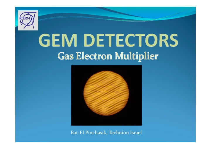

Bat-El Pinchasik, Technion Israel
GEM detectors main element GEM foil Terminals 10 cm Kapton (polyimide) p (p y ) copper-clad on both sides
CO2+ Argon CO2+ Argon CO2+ Argon CO2+ Argon GEM GEM DRIFT REGION INDUCTION REGION REGION Tracking, segmentation Triggering Etc ..
Field lines Electrons follow the Drift field field lines In the GEM foil 500 volts holes: high 50 μ m density of y field lines Induction Induction field Electrons gain energy!
Si Simulation: l ti CATHODE Ions Ions Electron-Ion pair pa Drift field Drift field Top GEM Bottom B Electrons are shared between between bottom Induction GEM and field anode anode Gain of the detector ANODE
Advantages Advantages Detector Area Cost Rate Aging g g covered (per area) capability process by a d detector Low aging GEM $$ d detector Gain loss and Gain loss and Wi Wire $ discharges chamber increase Noise and Silicon leakage detectors detectors current t increase
72µm • First invented in 1998 40 µm • Double conical geometry Doub e co ca geo et y • Used already in several experiments e pe e s copper 98.9 µm • Easy to produce Easy to produce kapton • larger detectors • low cost per area low cost per area 42.5 µm µ copper
Gl Glance from above f b Internal & External External 140 µm diameter Larger smaller diameter diameter diameter diameter 140 µm
See the difference Large conical GEM conical GEM foil 60 cm 10 X 10 cm
CO2+ Argon CO2+ Argon CO2+ Argon CO2+ Argon Voltage Voltage over the GEM GEM Drift field Induction Induction Anode current d field
D ift fi ld Drift field scan GEM voltage: 500 volts g 5 E induction: 3 (kv/cm) I anode I anode I anode conycal conical (normalized) (normalized) (normalized) 1 standard 0.8 plateau 0.6 Recombination Electrons end up in Top GEM 0.4 0.2 E drift (V lt / (Volts/cm) ) 0 0 1000 2000 3000 4000 5000
G i Gain vs. GEM voltage GEM lt Integration over Integration over Gain Gain distance α α Townsend Field & gas g coefficient properties Gain of standard the conical conical detector 500 Log E induction: scale 3kv/cm E drift: 2 kv/cm 50 50 Gem voltage 5 (volt) 300 350 400 450 500 550 600 650
Induction scan d i Electrons distribution I anode I d (normalized) 1.1 conical standard 1 0.9 0 8 0.8 0.7 0.6 Higher Higher signal More 0.5 electrons get to the anode 0.4 Increasing 0.3 induction field 0.2 0.1 E induction 0 1000 2000 3000 4000 5000 6000 7000 (volt/cm)
C Conclusions l i • Conical GEM has similar performance as standard GEM Results • Low cost Low cost • Larger area Advantages • Easy to fabricate • Conical GEM is an attractive candidate to C i l GEM i tt ti did t t future LHC upgrades Conclusion
C Current applications t li ti LHCB TOTEM COMPASS LHCB muon And the future? And the future?
Recommend
More recommend