Based on the Reynolds number similarity, water is 2 ( m m ) - PDF document
Transactions of the Korean Nuclear Society Virtual Spring Meeting July 9-10, 2020 Design of the Perforated Plate Improving Flow Uniformity in the SFR Steam Generator V.T. Nguyen a , S. Im b* , J. Jung c , S.R. Choi c , and B.J. Kim a* a School of
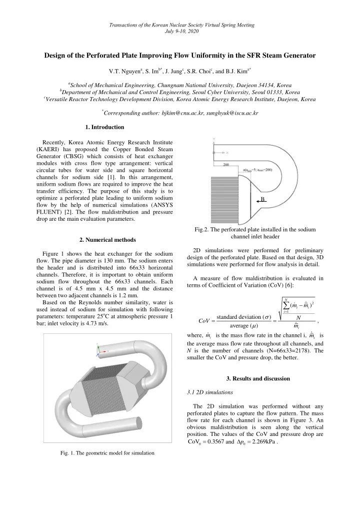
Transactions of the Korean Nuclear Society Virtual Spring Meeting July 9-10, 2020 Design of the Perforated Plate Improving Flow Uniformity in the SFR Steam Generator V.T. Nguyen a , S. Im b* , J. Jung c , S.R. Choi c , and B.J. Kim a* a School of Mechanical Engineering, Chungnam National University, Daejeon 34134, Korea b Department of Mechanical and Control Engineering, Seoul Cyber University, Seoul 01333, Korea c Versatile Reactor Technology Development Division, Korea Atomic Energy Research Institute, Daejeon, Korea * Corresponding author: bjkim@cnu.ac.kr, sunghyuk@iscu.ac.kr 1. Introduction Recently, Korea Atomic Energy Research Institute (KAERI) has proposed the Copper Bonded Steam Generator (CBSG) which consists of heat exchanger modules with cross flow type arrangement: vertical circular tubes for water side and square horizontal channels for sodium side [1]. In this arrangement, uniform sodium flows are required to improve the heat transfer efficiency. The purpose of this study is to optimize a perforated plate leading to uniform sodium B flow by the help of numerical simulations (ANSYS FLUENT) [2]. The flow maldistribution and pressure drop are the main evaluation parameters. Fig.2. The perforated plate installed in the sodium channel inlet header 2. Numerical methods 2D simulations were performed for preliminary Figure 1 shows the heat exchanger for the sodium design of the perforated plate. Based on that design, 3D flow. The pipe diameter is 130 mm. The sodium enters simulations were performed for flow analysis in detail. the header and is distributed into 66x33 horizontal channels. Therefore, it is important to obtain uniform A measure of flow maldistribution is evaluated in sodium flow throughout the 66x33 channels. Each terms of Coefficient of Variation (CoV) [6]: channel is of 4.5 mm x 4.5 mm and the distance between two adjacent channels is 1.2 mm. N Based on the Reynolds number similarity, water is 2 ( m m ) i i used instead of sodium for simulation with following i 1 parameters: temperature 25 o C at atmospheric pressure 1 standard deviation ( ) N CoV , bar; inlet velocity is 4.73 m/s. average ( ) m i where, m is the mass flow rate in the channel i, m is i i the average mass flow rate throughout all channels, and N is the number of channels (N=66x33=2178). The smaller the CoV and pressure drop, the better. 3. Results and discussion 3.1 2D simulations The 2D simulation was performed without any perforated plates to capture the flow pattern. The mass flow rate for each channel is shown in Figure 3. An obvious maldistribution is seen along the vertical position. The values of the CoV and pressure drop are C V o 0. 356 7 and p 2.269kPa . 0 0 Fig. 1. The geometric model for simulation
Transactions of the Korean Nuclear Society Virtual Spring Meeting July 9-10, 2020 Fig. 5. Velocity contour at distance a=100mm (B view in Figure 2) The hole diameters are calculated according to the Fig. 3. Mass flow rate for each channel when no plate is proposed formula: added. Then, the perforated plates with uniform holes v 5 d d (diameter=4.5mm) were installed in the inlet header or i 5 v i both the inlet header and outlet header. The effect of the where, d is the hole diameter for i-th level velociy plate distance from the channel on the CoV and i pressure are plotted in Figure 4. There is the optimal magnitude. position of the perforated plate in terms of CoV, which d is the smallest diameter corresponding to the 5 is the smallest when the plate is placed in the middle of maximum velocity magnitude ( d = 2.5 mm). 5 the inlet or outlet headers. This result is consistent with v is average value of velocity magnitude of i-th J. Wen et al. [4]. The plate distance of 100 mm is used i level. for 3D simulation. The thickness of the plate is 5 mm and the distance between the holes is 2 mm. The design of the perforated plate is shown in Figure 6. Fig. 4. The change of CoV and pressure according to distance a. 3.2 3D simulations Fig. 6. The design of the perforated plate. A 3D simulation without any plates was conducted to Simulation results are given in the Table I. One can obtain the velocity contour in the position where the see clear favorable effects of the plates. CoV is perforated plates will be placed. Figure 5 shows the significantly decreased at a little cost of the pressure velocity magnitude divided into 6 levels. drop.
Transactions of the Korean Nuclear Society Virtual Spring Meeting July 9-10, 2020 characteristics of a plate fin heat exchanger ”, International Table I: Values of CoV and pressure drop Journal of Thermal Sciences, Volume 126, April 2018. Increase Reduction p in Case CoV in CoV pressure (kPa) (%) drop (%) No plate 0.3094 - 2.7408 - Adding 0.0751 75.73 2.9462 7.49 1 plate Adding 0.0706 77.18 3.1852 16.21 2 plates 4. Conclusions This paper has presented the numerical simulation to determine the optimal design of the perforated plate to improve the flow uniformity throughout the sodium channels. The proposed design was shown to be excellent to improve heat transfer efficiency in the Copper Bonded Steam Generator. Acknowledgements This work was supported by the National Research Foundation of Korea (NRF) funded by Ministry of Science and ICT (Grant No. NRF- 2020M2A8A6018468). REFERENCES [1] R. W. Fox, A. T. McDonald, P. J. Pritchard, J. W. Mitchell, “ Fluid Mechanics, 9th Edition SI Version ” , Willey, pp. 245- 269; 294-297, 2016. [2] ANSYS, Ansys Fluent Theory Guide, 19.2, 2018. Release. [3] S. Im, J. Hong, S.H. Ryu, J.W. Han, S.R. Choi, “ Conceptual Design of Copper Bonded Steam Generator to minimize Sodium-water Reaction ” , Korea Atomic Energy Research Institute, 2019. [4] J. Wen, Y. Li, S. Wang, A. Zhou, “ Experimental Investigation of Header Configuration Improvement in Plate- fin Heat Exchanger ” , Applied Thermal Engineering, Vol. 27, pp. 1761-1770, 2007. [5] B.W. Lance, M.D. Carlson “Printed Circuit Heat Exchanger Flow Distribution Measurements”, Proceedings of ASME Turbo Expo 2017: Turbomachinery Technical Conference and Exposition GT 2017, Charlotte, NC, USA, 2017 June 26-30. [6] S. Baek, C. Lee, S. Jeong “ Effect of Flow Maldistribution and Axial Conduction on Compact Microchannel Heat Exchanger ” , Cryogenics, pp. 49-61, 2014. [7] W.M kays, A.L. London “Compact Heat Exchangers, third edition”, McGraw -Hill, New York, 1984. [8] Ting Ma , Pan Zhang, “ Prediction of flow maldistribution in printed circuit heat exchanger ”, International Journal of Heat and Mass Transfer, Volume 152, May 2020. [9] Sanjeev Kumar, Pawan Kumar Singh , “ Effects of flow inlet angle on flow maldistribution and thermal performance of water cooled mini-channel heat sink ”, International Journal of Thermal Sciences, Volume 138, April 2019. [10] Karima Boukhadia, Houari Ameur , “ Effect of the perforation design on the fluid flow and heat transfer
Recommend


More recommend
Explore More Topics
Stay informed with curated content and fresh updates.