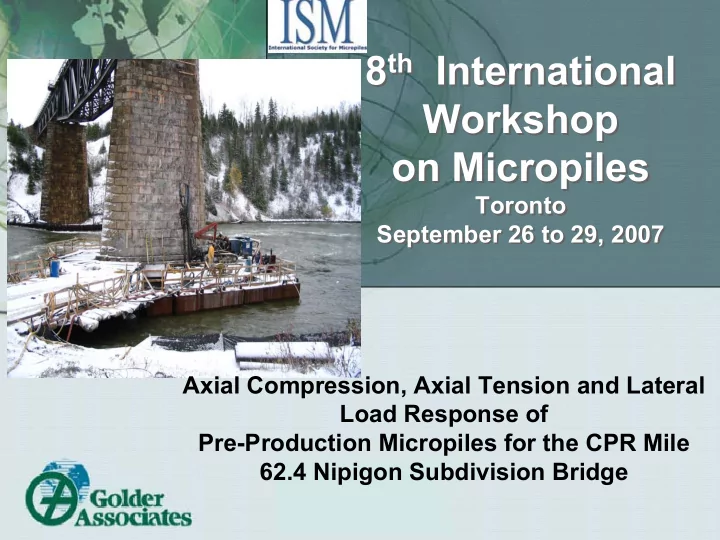

8 th International 8 th International Workshop Workshop on Micropiles on Micropiles Toronto Toronto September 26 to 29, 2007 September 26 to 29, 2007 Axial Compression, Axial Tension and Lateral Load Response of Pre-Production Micropiles for the CPR Mile 62.4 Nipigon Subdivision Bridge
Case History Case History � Underpinning and jacketing of existing Canadian Pacific Railway (CPR) bridge foundations at Mile 62.4, Nipigon Subdivision (near Thunder Bay, Ontario) • Capital cost savings of 20 % compared to replacement. • First of its kind project in Canada. � Approximately 130 year old structure • Steel Superstructure • Stone Masonry Piers (3 Piers) • Timber Piles and Mat Foundations (overstressed)
Project Team Project Team � Canadian Pacific Railway (Owner) � Golder (Geotechnical Consultant, Micropile Designer and Construction Monitoring) • Donald Bruce (Advisor) � HMM (Construction Manager) � LAS (General Contractor) � GFC (Micropiling Contractor) • Isherwood Associates
Golder Project Team Golder Project Team � Calgary • Dennis Becker • Peter Thomson • Blake Leew � Mississauga • Paul Dittrich • Arash Zakeri � Saskatoon • Greg Misfeldt • Dean Lorras
Ground Conditions Ground Conditions � Pier 1 • Sand, cobbles and masonry rubble fill • Compact to dense sand and gravel • Compact to very dense silt • Very stiff silty clay � Pier 2 • Compact to dense sand and gravel • Compact to very dense silt � Pier 3 • Sand, cobbles and masonry rubble fill • Compact to dense sand and gravel • Dense to very dense silt
Design Criteria (Single Pile) Design Criteria (Single Pile) � Service loading conditions: • Maximum axial load = 1,200 kN • Maximum lateral load = 100 kN • Maximum moment = 100 kN-m � At design serviceability loading: • Settlement ≤ 6 mm • Differential settlement ≤ 3 mm • Lateral displacement ≤ 13 mm
Design and Analysis Design and Analysis � Preliminary micropile sections and lengths selected using conventional methods � Micropile sections and lengths refined and finalized using 3D finite element program ( FB-Pier ) � Manual checks following AREMA
Micropile Section Details Micropile Section Details � Total pile lengths varied between 17.9 m (Pier 3) and 20.6 m (Pier 2) • Outer steel casing: – 273 mm diameter ; 5.8 m to 9.3 m long – 13 mm wall thickness • Central steel reinforcement: – DSI #20 (69 mm diameter) threadbar – 80 ksi (551 MPa) • Additional inner casing at Pier 1: – to resist high bending moments – 168 mm diameter and 6.6 m long – 9.5 mm wall thickness
Pre-Production Load Testing Pre-Production Load Testing � Important to load axially to failure to determine ultimate bond values for: • Verification of design assumptions and installation methodology • Assess if micropiles lengths and/or diameters can be reduced � Instrumentation adds value in refining design and understanding behaviour:
Installation Methodology Installation Methodology � Duplex drilling system with eccentric down-hole hammer
Micropile Load Testing Micropile Load Testing � Pre-production axial load tests: • Compression Test to 2.5 DL (3000 kN) • Lateral Test to 2.5 DL (250 kN) • Tension Test to 2.3 DL (2760 kN) • Two Sets (East Side and West Side) � Proof Tests: • Tension Test to 1.3 DL (1560 kN) • 12 piles tested (4 at each pier)
Compression Test Compression Test
Compression Test Results – East Side Compression Test Results – East Side 3500 Total Displacement 3000 Theoretical Elastic Response, Full Length Theoretical Elastic 2500 Response, Cased Length Axial Load, kN 2000 1500 1000 Micropile CE-2 (Pier 1) 500 Avg. Bond = 220 kPa (post- grouted) 0 0 5 10 15 20 25 30 35 40 Axial Displacement, mm
Tension (Uplift) Test Results Tension (Uplift) Test Results 3000 2500 2000 Axial Load, kN 1500 1000 Pile R-E2 (Pier1) 500 Avg. Bond = 150 kPa (No post- grouting) 0 0 10 20 30 40 50 60 70 Displacement, mm
Compression Test Results – West Side Compression Test Results – West Side 4000 Micropile C-W (Pier 3) 3500 Avg. Bond = 350 kPa (post-grouted) 3000 2500 Axial Load, kN 2000 1500 Total Displacement 1000 Theoretical Elastic Response, Full Length 500 Theoretical Elastic Response, Cased Length 0 0 5 10 15 20 25 30 35 40 Displacement, mm
Comparison Between Design and Comparison Between Design and Measured Bond values Measured Bond values � Pier 3 (Sand and Gravel): Design Value = 140 and 250 kPa Measured Value = +190 to 350 kPa � Pier 1 (Dense Silt): Design = 190 kPa Measured = +150 to 220 kPa
Lateral Load Test Lateral Load Test Piles Instrumented with In-Place Inclinometers
Lateral Test Results Lateral Test Results -1 Ground Surface 0 1 2 Depth, m 3 4 5 LR-E1 Pile response was LL-E1 Predicted (design) stiffer than 6 -5 0 5 10 15 20 25 expected Horizontal Displacement, mm
Proof (Uplift) Axial Load Tests Proof (Uplift) Axial Load Tests
Proof Test Results Proof Test Results CPR Mile 62.4 Nipigon: Proof Tests 25.00 20.00 Movement (mm) 15.00 10.00 5.00 0.00 0 200 400 600 800 1000 1200 1400 1600 1800 Load (kN) P2-2 P2-7 P2-11 P3-24 P2-8 P3-10 P3-3 P3-18 P1-34 P1-31 P1-3 P1-14
Test Results Summary Test Results Summary � Failures were not induced during pre- production load tests � Pre-production results confirmed design bond estimates and micropile sections and lengths � Proof tests satisfied acceptance criteria developed by CPR
Summary Summary � Micropiles successfully applied as a cost-effective foundation upgrade system � Proven resistance to high axial and lateral loads and to applied moments � Existing state-of-practice and tools appear to be sufficient for design purposes
QUESTIONS? QUESTIONS?
Recommend
More recommend