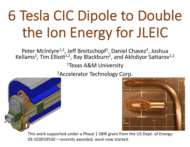

6 6 Tesl sla CIC Dipole to Double th the Ion on Energy for or JLEIC IC Peter McIntyre 1,2 , Jeff Breitschopf 1 , Daniel Chavez 2 , Joshua Kellams 2 , Tim Elliott 1,2 , Ray Blackburn 2 , and Akhdiyor Sattarov 1,2 1 Texas A&M University 2 Accelerator Technology Corp. This work supported under a Phase 1 SBIR grant from the US Dept. of Energy: DE-SC0019550 – recently awarded, work now started.
Mo Motivation: JLEIC’s collision energy limits its cov overage of EIC physics The NRC report compared the luminosity vs collision energy for the physics objectives of EIC in the two competing designs. JLEIC 6 T JLEIC 3 T JLEIC eRHIC Yuhong calculated the luminosity vs c.m. energy for several choices of dipole field in the Ion Ring. A 6 T Ion Ring would provide excellent coverage for all of the EIC physics objectives.
TA TAMU has developed the 3 T JLEIC dipole ba based d upo upon n NbT bTi cabl ble-in in-co conduit. cross-section of 15-strand NbTi CIC End region of the 3 T CIC dipole; Quadrant cross-section of 3 T CIC dipole for JLEIC – FRP structural beam; motorized bend fixture used to form the flared ends.
TA TAMU tr transferred th the ca cable te technology to to AT ATC and and Hy HyperTech CIC manufacturing process at ATC: 24-spool stranding machine; b) SS foil over-wrap Drawing of sheath onto cable Completed 125 m length of CIC. ATC now manufactures 140 m CIC cables suitable for a complete 4 m 3 T JLEIC dipole. The cabling facility has 24-spool capacity, and can accommodate the 2-layer CIC for the 6 T dipole presented below.
Mo Moti tivated by by the the NR NRC ch challen enge, e, we we ha have de designe ned a 6 T di dipo pole us using ng 2-la layer CIC. 19 turns 71 turns 7.8 cm 2 NbTi wire 13.7 cm 2 NbTi wire Quadrant cross-section of the 6 T cos q dipole Quadrant cross-section of a CIC-based 6 T dipole with the same aperture and performance as the SIS300 cos q dipole developed for SIS300 by IHEP and GSI: 1-coil, 2- spacer wedges, 3-key, 4-collars, 5-pin, 6-yoke, 7- green – G-11 structure elements, blue – steel flux return. outer cylinder, 8-weld.
Fl Flar ared ed end nd geo eometry, 2-la layer CIC IC Sample of 2-layer CIC, bent on 61 mm bend radius. Cutaway of the end region of the 6 T CIC dipole, showing the end windings and the FRP structure.
Ma Magnetic design of the 6 T dipole Multipoles vs. field Load line
Fl Flux ux pl plate e suppr uppres esses es per persisten ent- cu curr rren ent multipoles es, snap ap-bac back At low-field excitation of superconducting dipoles (injection), the ramp-down induces current loops in the superconducting filaments of all the wires in the windings. Those current loops drive multipole fields that de-stabilize the beam at injection. We locate horizontal steel flux plates over/under the beam tube. The flux plates create a dipole boundary condition that suppresses such multipoles. Quantitative simulation for the 3 T JLEIC dipole shows x5 suppression of snap-back. The flux plate preserves the low-field performance for the 6 T dipole – protons can still be injected at 8 GeV then accelerated to 200 GeV.
Systematic ic develo lopment of 2-la layer cable le • We develop a new cable by fabricating short lengths by hand in the lab: • Layer 1 wires wound with CW twist pitch • First CCW over-wrap • Second CW over-wrap • Layer 2 wires wound CCW • Draw sheath to optimum compactness, Bend on 60 mm radius, dissect
Sp Splice ce joint to connect ect CIC IC to Ruther erford cable e lea eads s and sp splice ce CIC IC First in CAD, Then using 3D printing to work out details, Next with Cu, SS, and CIC
The 6 T dipole prov ovides a major co competitive benef efit for JLEIC But what does it cost? Main cost-driver parameters of 5 dipole designs. cos q dipoles CIC dipoles Dipole BNL RHIC 1-shell IHEP SIS300 2-shell TAMU/ATC CIC 3T ATC CIC 6T Operating field 4 4 6 3 6 T Aperture 8 dia. 10 dia. 10 dia. 10 x 6 10 x 6 cm # turns/pole 32 40 71 12 19 Wire cross- 3.2 4.0 13.7 2.0 7.8 cm 2 section/pole From Willen’s cost model, the 6 T dipole should cost ~twice as much as the 3 T CIC dipole.
Con Conclusion ons • TAMU and ATC are developing a 2-layer NbTi CIC and a 6 T dipole suitable for JLEIC requirements. • The CIC development is going well – we expect to qualify it for performance requirements in Phase 1. • The CIC bend tools are being upgraded to handle the much stiffer 2-layer CIC. • A Phase 2 effort will be proposed in which we build a short-model 6 T dipole and test it at BNL test facility. • We will need JLab’s support in the competition for Phase 2 funding.
Recommend
More recommend