
SLIDE 1
2 Axis CNC Plasma Cutter CNC CNC or computer numerical control is a - - PowerPoint PPT Presentation
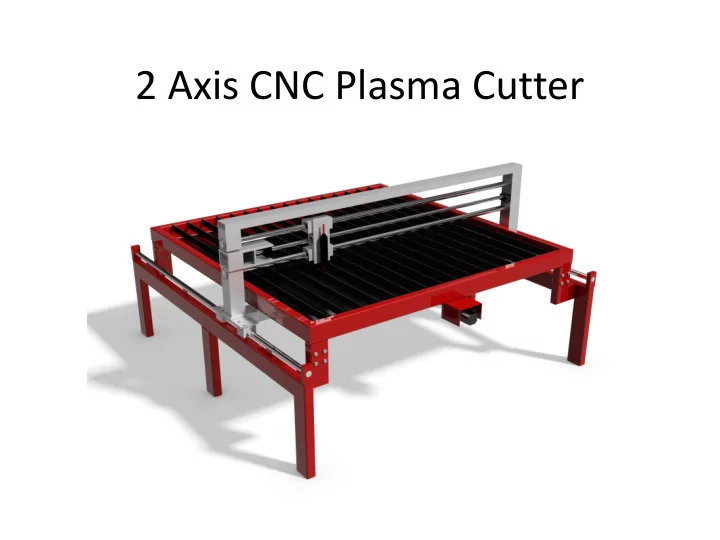
2 Axis CNC Plasma Cutter CNC CNC or computer numerical control is a way to control machine tools via a computer In this project I will be making a CNC 2 Axis platform for a plasma cutter CNC makes it possible to cut more complex
2𝜌𝜘𝑈 𝑚
2∗𝜌∗0.9∗4𝑂𝑛 10 𝑛𝑛
[1]:Roton Products, Inc. Ballscrews and Ballnuts [Online]. Available: http://www.roton.com/page.aspx?id=28
Illustration of Ballnut and Ballscrew [1] I ordered my ballscrews online from china and have had trouble with the seller, they have not arrived which is the reason I did not finish the machine yet The photo above shows the inner workings of the ballnut and ballscrew system
Initial asymmetric design
[2]: A.H.Slocum. Fundamentals of Design. MIT, Cambridge, Massachusetts 2007
𝑡𝑢𝑓𝑞 ∗200𝑡𝑢𝑓𝑞𝑡 𝑠𝑓𝑤
10𝑛𝑛
𝑠𝑓𝑤
𝑞𝑣𝑚𝑡𝑓𝑡 𝑛𝑛