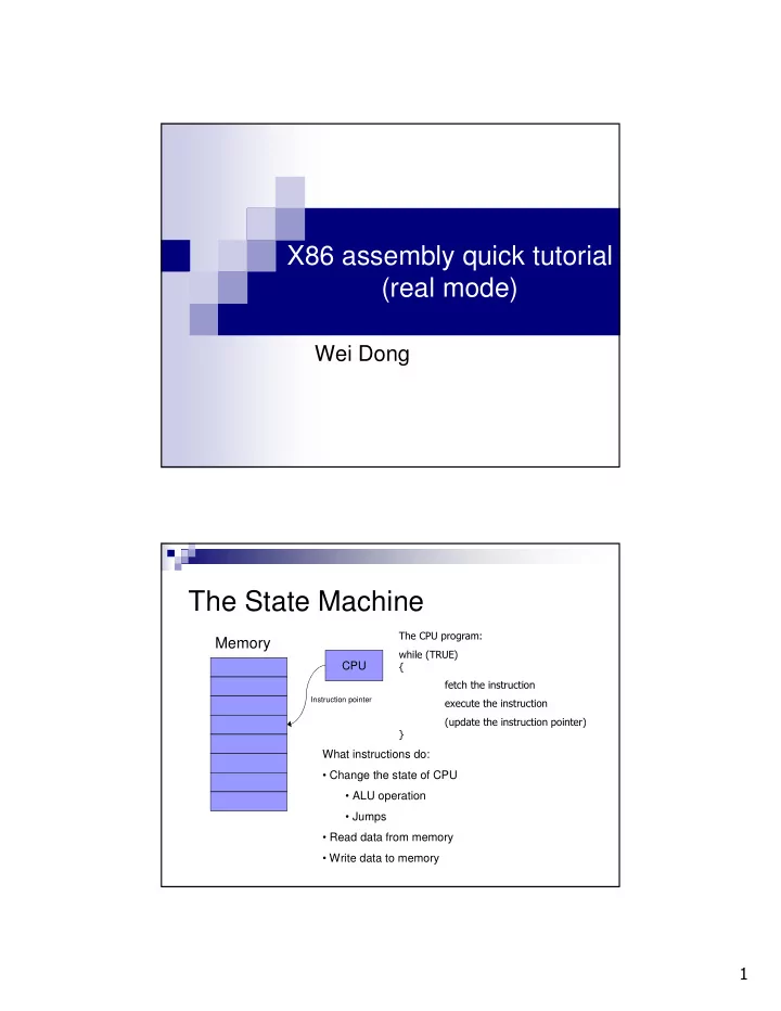

X86 assembly quick tutorial (real mode) Wei Dong The State Machine ���������������� Memory ������������ CPU � ��������������������� Instruction pointer ����������������������� �������������������������������� What instructions do: • Change the state of CPU • ALU operation • Jumps • Read data from memory • Write data to memory �
CPU State: Register Set General-purpose registers 16bit 32bit Segment registers (16bit) AH AL AX EAX CS BH BL BX EBX DS CH CL CX ECX SS DH DL DX EDX ES BP EBP FS SI ESI GS DI EDI Instruction Pointer (32bit) Flags (32bit) SP ESP EFLAGS EIP Address the register by: %ax, %ebx, etc A little bit on EFLAGS Function of EFLAGS: • Control the behavior of CPU • Save the status of last instruction Bit Name Comment 0 CF: carry flag 6 ZF: zero flag 7 SF: sign flag 9 IF: interrupt sti; cli; 10 DF: direction std; cld; 11 OF: overflow !
Memory Addressing Format: segment:displacement(base, index) Offset = Base + Index + Displacement Address = (Segment << 4) + Offset Displacement: constant Base: %bx, %bp Index: %si, %di Segment: %cs, %ds, %ss, %es Memory Addressing (data) segment:displacement(base, index) � The components are all optional � Default segment: � %bp: %ss � %bx, %si, %di: %ds � Examples 100 (%si) = %ds:(%si) (%bp) = %ss:(%bp) (%bx,%si) = %ds:(%bx,%si) -10(%bp) = %ss:-10(%bp) %ds:-10(%bx, %si) "
Instructions: arithmetic & logic � add/sub{l,w,b} source, dest � inc/dec/neg{l,w,b} dest � cmp{I,w,b} source, dest � and/or/xor{l,w,b} source, dest … � Restrictions � No more than one memory operand Instructions: Data Transfer � mov{lwb} source, dest � xchg{lwb} source, dest � Segment registers can only appear with registers � movsb � movb %ds:(%si) %es:(%di) � %si � %si + inc If DF = 0 then inc = 1 � %di � %di + inc else inc = -1 � %cx � %cx $ 1 � Often used with %cx to move a number of bytes #
Example � Move 0x200 bytes from 0x0100:0x0000 to 0x0080:0x0000 movw $0x0100, %ax movw %ax, %ds /* setup %ds */ movw $0x0080, %ax movw %ax, %es /* setup %es */ movw $0, %ax movw %ax, %si /* setup %si */ movw %ax, %di /* setup %di */ movw $0x200, %cx cld /* setup direction flag */ repeat: movsb cmp $0, %cx jnz repeat Example (cont.) � Move 0x200 bytes from 0x0100:0x0000 to 0x0080:0x0000 movw $0x0100, %ax movw %ax, %ds /* setup %ds */ movw $0x0080, %ax movw %ax, %es /* setup %es */ movw $0, %ax movw %ax, %si /* setup %si */ movw %ax, %di /* setup %di */ movw $0x200, %cx cld /* setup direction flag */ rep movsb %
Instructions: stack access � pushw source � %sp � %sp – 2 � %ss:(%sp) � source � popw dest � dest � %ss:(%sp), dest � %sp � %sp + 2 � Setup up the stack before you actually use it Instructions: unconditional jump � jmp label � %ip � label � ljmp NEW_CS, offset � %ip � label; %cs � NEW_CS � call label � push %ip + ? (address of call instruction) � %ip � label � ret � pop %ip � Also lcall and lret &
Instructions: conditional jump � j* label: jump to label if flag * is 1 � jn* label: jump to label if flag * is 0 � *: bits of %eflags Examples: js, jz, jc, jns, jnz, jnc, … BIOS Service � Use BIOS service through interruption � Store the parameters to the registers � Call the interruption � int INT_NUM '
Example: BIOS INT 0x13 Function 2 � ah = 2 � al = number of sectors to read � ch = cylinder number bits 0-8 � cl, bits 6&7 = cylinder number bits 8-9. � bits 0-5 = starting sector number, 1 to 63 � dh = starting head number, 0 to 255 � dl = drive number � es:bx = pointer where to place information read from diskette � Returns: � ah = return status (0 if successful) � carry = 0 successful, = 1 if error occurred Note for project 1 � In our project, the bootloader is working in real mode (16 bits). � Bootloader code is loaded by BIOS, so it did not have %ds, %ss, %sp setup properly when it is loaded. � In bootloader, all the code and data share the same 512 bytes. So data will have the same segment as code. (
Recommend
More recommend