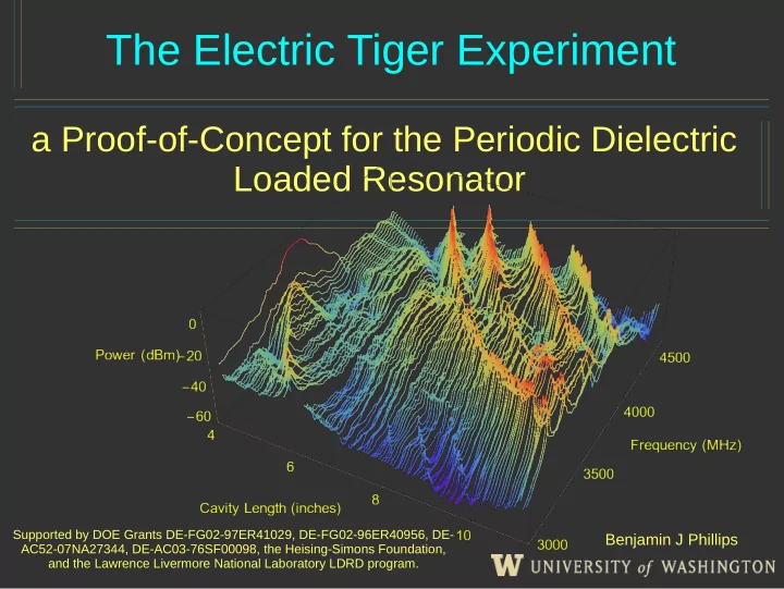

The Electric Tiger Experiment a Proof-of-Concept for the Periodic Dielectric Loaded Resonator Supported by DOE Grants DE-FG02-97ER41029, DE-FG02-96ER40956, DE- Benjamin J Phillips AC52-07NA27344, DE-AC03-76SF00098, the Heising-Simons Foundation, and the Lawrence Livermore National Laboratory LDRD program.
Motivation Design Goals • Experiment to search high frequency regions ( 4 – 7 GHz ) • Rapid prototyping with on-hand materials • Cavity is reasonably simple to tune (e.g. manageable mode crossings ) • Lay foundations for experiments that rely on dielectrics ( very high frequency searches )
Motivation The P.D.L.R. Design • Makes use of dielectric media inside a resonant cavity • Dielectric media compresses wavenumber – prevents form-factor integral from going to zero
Motivation Laying Foundations • Resonant cavities that use dielectrics are difficult to tune – dielectrics have to be moved in unison • Tuning procedures developed by Electric Tiger can be used by these types of experiments ( e.g. Orpheus )
Implementation Construction of Cavity • Rectangular waveguide with one stationary antenna, one movable • Dielectric media is provided by three nylon blocks • Tuning is provided by scissor-jack and stepper motor driving auger screw • Cavity length is measured by string potentiometer • Cavity design limits mode Quality Factor
Implementation Magnetic Field • Rectangular cavity geometry permits use of constant z- axis magnetic field • Magnetic field provided by 1.54 Tesla DC Magnet
Cavity Structure Implementation (Transmission) • Cavity has a non-trivial amount of static structure • Modes are broad and amplitude is not always significantly higher than static structure
Cavity Structure Implementation (Transmission) • Simulations of cavity determines mode that couples best with axion field • Mode moves over a wide frequency range, ~3.5 – 6.5 GHz, including regions currently blocked by RF components
Implementation Transmission • Static structure in transmission measurements makes modes difficult to follow • Q’s of ~ 250 • Traditional approaches (e.g. Lorentzian fitting) are unsuitable
Implementation Reflection • Reflection modes show much less static structure • Strategy: Identify and follow modes in reflection, switch to transmission to take data
Implementation Filtering • Even in reflection, traditional mode-tracking techniques are not appropriate • Simple band-pass filters either suppress actual peaks, or amplify static structure • Solution: Use non-linear filters – suppress noise while preserving peaks
Implementation Non-Linear Filters • Mode Identification scheme only needs heuristic idea of what a peak is • Criteria is ~ f’[n] < 0 & f’[n+1] > 0 • Since we only need a loose idea of what a peak is, namely that it is ‘sharp’, we can use filters that do not linearly modify signal power • Use bilateral filter, a specific example of a non- linear convolution
Implementation Non-Linear Filters Bilateral Filter Original Gaussian Blur • Effects of Bilateral filter are more obvious when looking at 2D figures • Low-pass filters ( Gaussian Blurs ) suppress noise, but erase features • Bilateral filter suppresses noise while preserving edges
Thoughts on Mode Implementation Maps • Why not rely on the mode map alone? • Electric Tiger has a high degree of mechanical slop • Modes tend to vanished at certain cavity positions • Goal is to divorce mode tracking procedure from mode map • Current mode tracking procedure uses mode map – real peaks can be ~ 175 MHz away from mode map
Data Collection Preliminary Results • Initial data run performed at room temperature • Exclusion limits set in 4-4.2 GHz Range using rudimentary equipment • Sensitivities of ~10 -9 • Mode tracking scheme was able to follow modes throughout tunable range • Experiment ran autonomously for ~8 days
Data Collection Preliminary Results
Data Collection Next Steps Projected Sensitivity for 8 week integration time • Initial data run made use of Signal Analyzer – collected ~10 5 points per spectra, averaged ~10 4 signals • Next data run will make use of digitizer – 10 8 points per spectra, virtually unlimited number of averages • Longer integration times • Cryogenic temperatures
High Performance “Side Effects” Signal Processing • Wide band-widths and fast digitization rates require very fast data processing • Use GPU for signal processing operations to keep up with data stream • GPU - accelerated methods are completely general and can be used by other experiments
“Side Effects” Analysis Procedures • Analysis procedure developed by Electric Tiger is generic • Applicable to wide variety of resonate cavity searches • May be incorporated into ADMX analysis in the near future
The two roles of Conclusion Electric Tiger • Platform to address concerns raised by other searches • Electric Tiger is validation of the P.D.L.R. Design – will search in unexplored axion-like particle parameter space
Recommend
More recommend