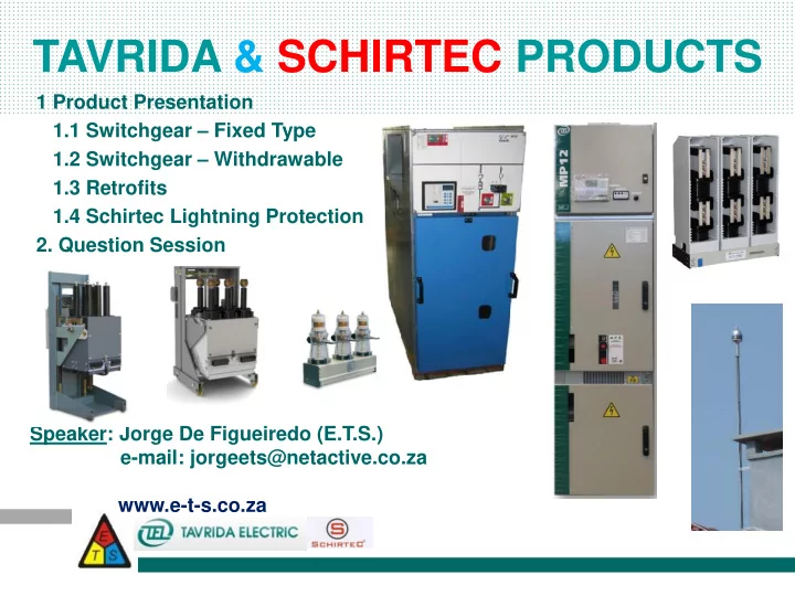

TAVRIDA & SCHIRTEC PRODUCTS 1 Product Presentation 1.1 Switchgear – Fixed Type 1.2 Switchgear – Withdrawable 1.3 Retrofits 1.4 Schirtec Lightning Protection 2. Question Session Speaker: Jorge De Figueiredo (E.T.S.) e-mail: jorgeets@netactive.co.za www.e-t-s.co.za
PRESENTATION OBJECTIVES 1. Present existing design and understand if design conception in principle acceptable for the client; 2. Present the directions in the development and understand potential market for each presented product; 3. Establish competitive target price; 4. Understand concerns of the client (service, price, availability, delivery time).
SWITCHGEAR Fixed Type Withdrawable
Switchgear – Fixed Type • Fix type panel with modular design • Small dimension with Load Break Switch in SF6 • Convenient and safe handling • Maximum access to connection points (removable door and roof) • Equipped with all necessary interlocks • Wide range of optional features
Low Voltage Compartment Front Panel
Withdrawable Type • Air insulated Switchgear solution • Cable connection points at comfortable height of up to 460mm • Pressure resistant inspection windows for cable and circuit breaker compartments • Typically with top-entry for cables or bus bars available • Equipped with all necessary interlocks • Different state-of-the-art switchgear models like: • With rear access • With a double busbar system • With front access only
VCB-DOU Low-Duty and High-Duty circuit breakers
Indication Circuit breaker DOU CLOSED/OPEN SERVICE/TEST Earthing switch CLOSED/OPEN
Arc Venting/Gas exhausts
Technical Specifications Rated voltage, kV 15 25 Rated insulated voltage, kV 15 24 Rated frequency, Hz 50/60 50/60 Rated power frequency withstand voltage, 1 min, kV 38 50 Rated lightning impulse withstand voltage, kV 95 125 Rated feeders Current, A 800; 1250; 2000; 2500; 800 Rated main busbar current, A 1250; 2000; 3150 1250; 2000 Rated breaking current, kA 25; 31,5 16 Rated short-time withstand current (3s), kA 25; 31,5 16 Rated peak withstand current, kA 82 40 Rated supply voltage for auxiliary circuits, V DC 24; 48; 110; 220 24; 48; 110; 220 AC 110; 220 110; 220 Insulation level Normal Normal Insulation type Air Air IAC classification (IEC62271-200) AFLR 31,5kA/1s AFLR 25kA/1s Busbar insulation Insulated Insulated Maintenance version Front/rear access Front/rear access Control version Local and RTU Local and RTU Height, mm 2248 2248 Width, mm 600 - 750 Up to 1250A 800…1250A 1000 2001…3150A 1251…2000A Depth 1350 1590 Class of protection IP 4X (IP 41 on request) IP 4X (IP 41 on request) Minimum ambient temperature -5 °C Maximum ambient temperature +40 °C Maximum altitude above sea level 1000 m*** Relative humidity 95% Ambient atmosphere in accordance with IEC 60721-2-1-"Wda": non-explosive, uncontaminated non-corrosive.
Typical Units / Compartments
DT-2-1250A / 800A / LK
FIXED PANELS TYPICALS
Photo Gallery
RETROFIT SOLUTIONS ISM/AG16-12-20/630-026 ISM/LMT-12-20/630-026
RETROFIT SOLUTIONS ISM/MOTOR ISM/SBV3-12-20/1000- ISM/SBV4-12-31.5/1250-112 STARTER-12- 067 20/1000-026
ISM/TEL-12-25/1250-150
ISM/TEL-12-20/630-150 18
ISM/TEL-12-20/630-150 Tavrida ISM series is the lightest and most compact medium voltage circuit breakers available on the market today. • All components are assembled along a single axis, with three mono-stable magnetic actuators (one per pole). • The actuators are mounted in a steel frame and are mechanically linked by a synchronizing shaft. • Long mechanical and interrupting lives • The actuators drive a pulling insulator that in turn connects to the advanced Tavrida vacuum interrupters at the top of the breaker. This single-axis design results in the highest reliability available today: Maintenance free with a total life expectancy of > 30 years, and up to 150,000 close - open operations. The Tavrida ISM can be installed in any orientation which makes it equally suitable to either new switchgear or retrofit applications. 19
Technical Specification EXISTING UNDER MAXIMUM RATINGS SOLUTION DEVELOPMENT Rated voltage (Ur) 12kV 12kV Rated power frequency withstand voltage (Ud) 28kV 28kV Rated lightning impulse withstand voltage 1.2/50 μsec (Up) To earth and between phases 75kV 95kV Over the insulated distance 75kV 95kV Rated Current 630A 800A; 1250A Rated short-circuit breaking current (Isc) 20kA 25kA Rated peak withstand current (Ip) 50kA 63kA Rated short-time withstand current (Ik) 20kA 25kA Rated duration of short circuit current (tk) 3s 3s Rated frequency 50/60Hz 50/60Hz Standards IEC 62271-100 IEC 62271-100 - 25…+40 - 25…+40 Temperature range Maximum relative humidity 95% 95% Maximum altitude 1000m a.s.l. 1000m a.s.l.
SCHIRTEC – Lightning Conductor 21
SCHIRTEC – Lightning Conductor • The air terminal has enough size and quality to conduct the biggest lightning strike. Ion generator, induction coil and the protector have high impedance. The generator is located inside of a special epoxy resin. So ion generator is protected from the environmental conditions. • Accelerator and atmospheric electrodes are designed in a way that can be charged with different potentials and with this feature, it is aimed to make work of the electrodes as both additional ionization producing resource and as accelerator. The regulation is made with the number of electrodes and ion generator’s impedance, lets the difference protection capacities in the SCHIRTEC E.S.E Lightning Conductors All Early Streamer Emission lightning conductors are tested in compliance with NF C 17-102 standard. 22
SCHIRTEC OPERATION The efforts which have been carried out until today to increase the radius of action of the lightning conductors were based mainly on the improvement of the excitation time of the upward leader. However, the effectiveness of a lightning conductor does not depend only on the excitation time of a leader to the rod but as well and above all of the capacity to propagate this leader on a large distance to capture the downward leader. SCHIRTEC has developed a new revolutionary generation of lightning conductor and thus keeps its technology advance. The operating principle of the SA 60µs consists, not only to initiate the upward leader, but moreover, provides enough energy to ensure its propagation until the junction with the downward leader. 23
Any Queries Contact
Any Queries Contact
Recommend
More recommend