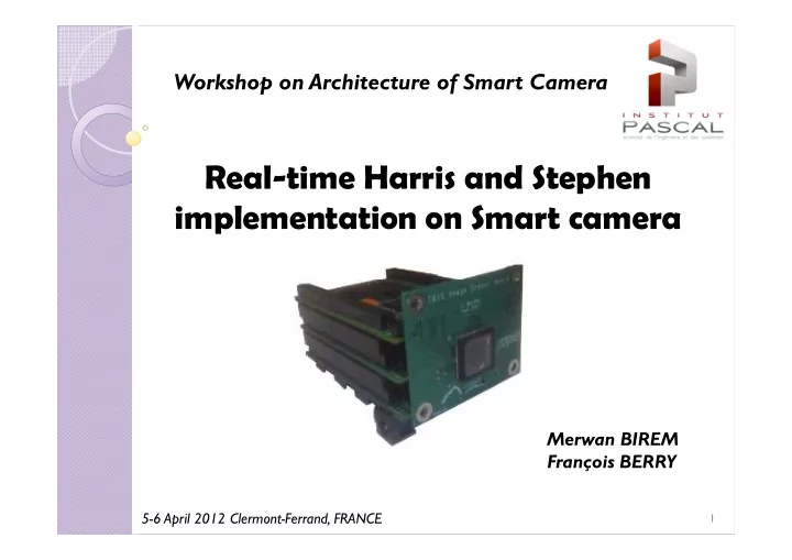

Workshop on Architecture of Smart Camera Real-time Harris and Stephen implementation on Smart camera Merwan BIREM François BERRY 5-6 April 2012 Clermont-Ferrand, FRANCE 1
Summary 1 - Feature Extraction, 2 - Harris & Stephen detector, 3 – The hardware implementation, 3 – The hardware implementation, 4 – The results of the implementation, 5 – The DreamCAM, 2
1 - Feature Extraction : is used to describe the combination of feature detector , and a feature descriptor. Feature descriptor A simple descriptor, which Feature detector gives for each interest point Harris & Stephen algorithm an intensity patch from the an intensity patch from the image (its neighbors). 3
2 - Harris & Stephen detector (1988) : 1/2 Currently, most of the computer vision algorithm use interest point of type Harris & Stephen as input. Because : � It is based on simple principal, � Gives acceptable results 4
2 - Harris & Stephen detector (1988) : 2/2 5
3 -The hardware implementation : 1/4 Sensing boards Communication • CMOS Imager, Board (Firewire) • Inertial devices FPGA board SeeMOS: FPGA SeeMOS: FPGA- -based smart cam based smart cam 6
3 -The hardware implementation : 2/4 Private memories (SRAM-10ns) Inertial Navigation Set: 1MB 1MB 1MB 1MB 1MB 3 accelerometers 3 gyrometers CMOS Imager 5 Data/@ 4 Mpixels Global FPGA FPGA memory memory /@ Data/@ ADC Softcore IEEE1394 Conversion control Windows of Interest control SeeMOS SeeMOS Synoptic Synoptic 7
3 -The hardware implementation : 3/4 light in data frame out 8
3 -The hardware implementation : 3/4 light in data frame out 9
3 -The hardware implementation : 3/4 light in data frame out 10
3 -The hardware implementation : 3/4 light in data frame out 11
3 -The hardware implementation : 3/4 light in data frame out 12
3 -The hardware implementation : 4/4 The data frame : 13
4 –The results of the implementation : 1/2 From the compilation report : (for image 256x256 pixels) � The maximal frequency = 22.52MHz, � The FPGA resources used : � The FPGA resources used : Logic Elements 11'327 / 57'120 20% Memory Bits 1'066'376 / 5'215'104 20% DSP-block 33 / 44 23% 14
4 –The results of the implementation : 2/2 15
5 –The DreamCAM Anatomy : Sensors board (GPS, inertial,…) Memory board 6 x 1Mb Cyclone III, FPGA IBIS5 1. 3Mpixels Image sensor Power board 16 16
Thanks For Your Attention 17
Recommend
More recommend