Protocol Stack and Layers Summary CSC 249 March 29, 2018 1 - PDF document
Protocol Stack and Layers Summary CSC 249 March 29, 2018 1 Chapter 6: Summary q Data link layer services: v error detection and correction v sharing a broadcast channel: multiple access v link layer addressing v Plug-and-play for ARP and switch
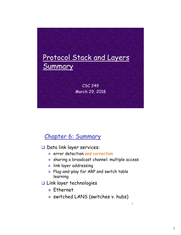
Protocol Stack and Layers Summary CSC 249 March 29, 2018 1 Chapter 6: Summary q Data link layer services: v error detection and correction v sharing a broadcast channel: multiple access v link layer addressing v Plug-and-play for ARP and switch table learning q Link layer technologies v Ethernet v switched LANS (switches v. hubs) 2 1
Encapsulation source message application M segment transport H t H t M network datagram H n H n H t M link frame H l H n H t M physical link H l H n H t M physical switch destination network H n H t M link H l H n H t M application M physical transport H t M network H n H t M router link H l H n H t M physical 3 Four sources of packet delay transmission A propagation B nodal queueing processing d total = d proc + d queue + d trans + d prop d trans : transmission delay: d prop : propagation delay: § L : packet length (bits) § d : length of physical link § s : propagation speed in medium § R : link bandwidth (bps) (~2x10 8 m/sec) d trans = L/R § § d prop = d / s d trans and d prop very different Introduction 1-4 2
Sockets q process sends/receives messages to/from its socket v sending process sends message through the socket v sending process relies on transport infrastructure, UDP or TCP as programmed into the operating system, to deliver the message to the socket at the receiving host & process application application socket controlled by process process app developer transport transport controlled network network by OS link link Internet physical physical Application Layer 2-5 DNS: a distributed, hierarchical database Root DNS Servers … … org DNS servers edu DNS servers com DNS servers umass.edu poly.edu pbs.org yahoo.com amazon.com DNS servers DNS servers DNS servers DNS servers DNS servers a host, or client, wants the IP address for www.google.com 1) Client (local server) queries root server to find the .com DNS server 2) Client queries .com DNS server to get google.com DNS server 3) Client queries google.com DNS server to get the IP address for www.google.com 2-6 3
TCP: slow start & congestion avoidance Implementation: q variable CWND q variable ssthresh q Loss event v Triple duplicate ACK v timeout 3-7 Transport Layer DHCP client-server scenario arriving DHCP server: 223.1.2.5 DHCP discover client src : 0.0.0.0, 68 dest.: 255.255.255.255,67 yiaddr: 0.0.0.0 transaction ID: 654 DHCP offer src: 223.1.2.5, 67 dest: 255.255.255.255 , 68 yiaddr: 223.1.2.4 transaction ID: 654 Lifetime: 3600 secs DHCP request src: 0.0.0.0, 68 dest:: 255.255.255.255, 67 yiaddr: 223.1.2.4 transaction ID: 655 time Lifetime: 3600 secs DHCP ACK src: 223.1.2.5, 67 dest: 255.255.255.255 , 68 yiaddr: 223.1.2.4 transaction ID: 655 Lifetime: 3600 secs yiaddr = ‘your internet address’ 8 broadcast address, 255.255.255.255 à sent to every host in the subnet 4
Router architecture overview routing routing, management forwarding tables computed, pushed to input ports processor control plane (software) forwarding data plane (hardware) high-seed switching fabric router input ports router output ports Routing: Dijkstra’s algorithm Step D(v),p(v) D(w),p(w) D(x),p(x) D(y),p(y) N' D(z),p(z) ∞ ∞ 0 2,u 5,u 1,u u 1 2,u 4,x 2,x ux ∞ 2 2,u 3,y uxy 4,y 3 3,y uxyv 4,y 4 uxyvw 4,y 5 uxyvwz 5 3 v w 5 2 u z 2 1 3 1 2 x y 1 Network Layer 5
CSMA/CD (collision detection) spatial layout of nodes Link Layer Slide Example: Creating an ARP Table For the same LAN segment: q ‘A’ wants to send datagram to ‘B,’ and B’s MAC address not in A’s ARP table. q ‘A’ broadcasts ARP query packet, containing B's IP address v Dest MAC address = FF-FF-FF-FF-FF-FF v All machines on LAN receive ARP query v ARP Packets contain IP & MAC address for source and destination v A caches (saves) IP-to-MAC address pair in its ARP table q B receives ARP packet, responds to A with its (B's) MAC address v Why does only ‘B’ respond? v frame sent directly to A’s MAC address (not broadcast) q ARP is “plug-and-play”: v nodes create their ARP tables without intervention from net administrator 12 6
Switch table example Suppose C sends frame to B switch address interface 1 A 1 3 2 B 1 2 E 3 G hub hub C 1 hu A b I F D G B C H E q Switch receives frame from from C v Notes that B and C are in same segment v Switch does nothing 13 Layer Protocols, and their Happens TO Packet Action caused BY packet Action/Event happens on main features own Application Transport Network Link 7
Recommend


More recommend
Explore More Topics
Stay informed with curated content and fresh updates.