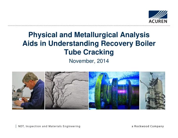

Physical and Metallurgical Analysis Aids in Understanding Recovery Boiler Tube Cracking November, 2014
PdM Technology – Infrared Thermography Gas Find IR – Example of LNG Leak Safety Minute
Economizer Tube Cracking Assessment • Leaks/Cracking occurring at tube-header interface • Visual inspection of tube sheet indicated various areas where shackles (hand cuff type) were damaged or missing • Various Testing Methods were used: – Strain Gauging – Forced Response Testing – Vibration Analysis – Digital Radiography – Scanning Electron Microscopy – In-Situ Metallography
Physical Testing • Natural frequency testing – completed to identify potential ranges of excitation • Vibration Testing on start up – to evaluate system vibration and potential results of soot blowing on response • Strain gage testing of selected tubes to determine load during operation • Digital Radiography to evaluate tube condition
Natural frequency Testing • Completed in cross channel format to verify accuracy • Identified many low level responses typical of a lightly restrained system
Baffle Plate Vibration Vibration trend over time showing response in the 175 Hz range – typical of resonance
Tube Vibration Vibration over time indicating vane pass vibration from the boiler feedwater pump.
Strain Analysis Fluctuations in strain on tubes over 600 second period Increase in strain on one tube as liquor added to the boiler
Testing Summary Observations: • Forced response data indicated heavily damped natural frequencies within the tubesheet. Resonance was not apparent. • Vibration levels due to air flow/thermal oscillations of the tubes were not noted within the vibration spectrum as they were low frequency and non synchronous. • Vibration due to soot blowing operation was not observed in the spectrum due to its low frequency. • Vibration at the vane pass frequency of the pump was observed on the tubes at low amplitude.
Testing Summary • Strain Gauges indicated fluctuations in strain with very low changes in temperature during boiler startup. Fluctuations were minimal as boiler reached steady state • MT indicated various locations of cracking at tube/header interface. • Bent tube sheet supports likely from thermal stresses on startup.
Structural Supports Deformation occurs due to thermal stresses within the tube sheet Damaged tube sheet support
Visual Testing Indication at header/tube interface MT completed on tube showing indication
Economizer Tube Leaks Light oxygen pitting apparent Weld repair noted along with crack on waterside (circled)
DR Image Waterside crack and repair evident Inlet Attachment End
Waterside Cracking Process
SEM – Water side Analysis SEM view of sectioned tube Waterside Cracks propagating from ID and contain corrosion product
Baffle Plate Failures Observations: • Examination of the baffle plate repairs indicated significant weld porosity and lack of penetration at various points. • Beach marks observed on several welds indicating fatigue failure. • Flow induced vibration exciting a natural frequency in the baffle. Oscillation was observed at 180 Hz (315 million cycles per year). • Embrittlement due to multiple welds at the same location.
Conclusions • Waterside cracking occurred due presence of oxygen. Cracks propagate from the inside out. Coupled with thermal transients on startup to provide mechanical strain necessary. • Fatigue cracking occurred due to loosening of shackles resulting in low amplitude oscillations of the tube sheet over an extended period. Cracks propagate from the outside in. – maintain shackles to prevent tube movement and fatigue • Fatigue failure of baffle plate welds were observed. Weld quality testing is important to verify correction quality
Recommend
More recommend