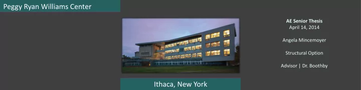
Peggy Ryan Williams Center AE Senior Thesis April 14, 2014 Angela Mincemoyer Structural Option Advisor | Dr. Boothby Ithaca, New York
Peggy Ryan Williams Center  Introduction AE Senior Thesis  Proposal April 14, 2014  Structural Depth  Gravity System Angela Mincemoyer  Lateral System Structural Option  Bridge Truss  Architectural Breadth Advisor | Dr. Boothby  Lighting Breadth  Conclusion Ithaca, New York
Peggy Ryan Williams Center  Introduction  Proposal Owner | Ithaca College Architect | Holt Architects  Structural Depth Structural Engineer | Ryan-Biggs Associates  Gravity System  Lateral System 58,200 GSF  Bridge Truss 4 Stories Substantial Completion | March 2010  Architectural Breadth Photo provided courtesy of Holt Architects  Lighting Breadth  Conclusion Introduction
Peggy Ryan Williams Center  Introduction Composite steel floor  Proposal 3” x 20 gauge composite metal deck 6” concrete slab  Structural Depth 48’  Gravity System Wide Flange Beams, girder, columns  Lateral System Irregular Layout  Bridge Truss Geometry, cantilevers  Architectural Breadth  Lighting Breadth  Conclusion Existing Gravity System
Peggy Ryan Williams Center  Introduction  Proposal Concentrically braced structural steel frames North-South  Structural Depth East-West  Gravity System Seismic Design Category A  Lateral System Wind Controlled Design  Bridge Truss  Architectural Breadth  Lighting Breadth  Conclusion Existing Lateral System
Peggy Ryan Williams Center  Introduction  Proposal Pratt Trusses  Structural Depth HSS  Gravity System 3.5” pipe  Lateral System Double Cantilever  Bridge Truss  Architectural Breadth  Lighting Breadth  Conclusion Existing Bridge System
Peggy Ryan Williams Center Scenario | Project Schedule is no longer critical Scenario | Learning opportunity  Introduction  Proposal Proposal | One way concrete slab system with Proposal | Two different redesign options will pan joists and girders be considered  Structural Depth  Beneficial for cantilevers  Reflection of New York’s  Gravity System historic covered bridges  Accommodates varying spans  Lateral System  Reflect on original name of & geometries  Bridge Truss the building  Thinner slab  Architectural Breadth (“The Gateway Building”)  Minimize architectural impact  Lighting Breadth  Conclusion Building Bridge
Peggy Ryan Williams Center Proposal| One way concrete slab system with Proposal| Two different redesign options will  Introduction pan joists and girders be considered  Proposal Goals| Design a one way concrete slab system Goals| After considering two redesign options:  Structural Depth  Determine which option to while:  Gravity System move forward with  Minimizing floor system depth  Lateral System  Design one side truss of the  Minimizing architectural impact  Bridge Truss bridge  Architectural Breadth  Lighting Breadth  Conclusion Building Bridge
Peggy Ryan Williams Center  Introduction  CRSI Manual  Proposal  Same joist size and spacing used throughout  Structural Depth  2 worst case spans considered  Gravity System  30” forms with 6” rib @ 36” o.c.  Lateral System  20” rib depth + 4.5” slab = 24.5” system depth  Bridge Truss  f ’c = 4,000 psi  Architectural Breadth  fy = 60 ksi  Lighting Breadth  Conclusion Pan Joist System
 8 Designed members indicated Peggy Ryan Williams Center D  Chosen due to: Long spans,  Introduction large tributary widths, high loadings  Proposal  Designed using spBeam  Strength requirements 2  Structural Depth  Deflections checked per ACI 318-11  Gravity System Table 9.5b 13  Lateral System  Bridge Truss  Architectural Breadth  Lighting Breadth Column Line D Column Line 2 Column Line 13 Column Line 8  Conclusion Framing Plan Girders/Beams
Peggy Ryan Williams Center  Designed using spColumn  Introduction  Both axial loads from above & moments were  Proposal applied  Structural Depth  Square section chosen  Gravity System  Ease of construction  Lateral System  Aid in future lateral system design  Bridge Truss  All column sizes were increased to  Architectural Breadth 18”x 18” for constructability  Lighting Breadth  Conclusion Columns
Peggy Ryan Williams Center  Introduction  Proposal  Columns & girders were removed from  Structural Depth original design  Gravity System  Floor system depth decreased by 5- 5/8”  Lateral System  Larger floor-to-ceiling height  Bridge Truss  Architectural Breadth  Lighting Breadth  Conclusion Summary Existing Redesign
Peggy Ryan Williams Center  Current lateral system  Introduction  Concentrically braced structural steel frames  Proposal  No longer the best option  Structural Depth  Gravity system may double as the lateral system  Gravity System  Concrete moment frames in North-South and  Lateral System East-West directions  Bridge Truss  4 concrete moment frames were considered in  Architectural Breadth each direction  Lighting Breadth  Conclusion Lateral System Introduction
Peggy Ryan Williams Center  Both wind and seismic forces were calculated per ASCE7-10  Introduction  Wind controlled  Proposal  Using spColumn , 18”x18” columns were  Structural Depth designed  Gravity System  Biaxial bending was considered  Lateral System  Worst case girder and joist were checked for  Bridge Truss beam-column interaction  Architectural Breadth  Found to be adequate  Lighting Breadth  Conclusion Lateral System Analysis
Peggy Ryan Williams Center  Introduction  Analysis was done using 4 frames in both  Proposal directions  Structural Depth  By adding frames the system will surely be  Gravity System adequate   Lateral System The gravity system of the building doubles as the lateral system  Bridge Truss  Architectural Breadth  Lighting Breadth  Conclusion Summary
Peggy Ryan Williams Center  Introduction  Sketches were produced to determine which  Proposal inspiration would be used in the redesign  Structural Depth  The covered bridge option was chosen  Gravity System  Box truss design  Lateral System  Move supports out to open up the space  Bridge Truss  Warren Truss  Architectural Breadth  Lighting Breadth  Conclusion Bridge Introduction
Peggy Ryan Williams Center  Introduction  Only gravity loads were considered for the side  Proposal trusses  Structural Depth  Panel point loads were determined based on layout  Gravity System   Lateral System Controlling Load Combinations:   Bridge Truss 1.2 D + 1.6 L + 0.5 S   Architectural Breadth 1.2 D + 1.6 S + L  Lighting Breadth  Conclusion Loads
Peggy Ryan Williams Center 1.2 D + 1.6 L + 0.5 S  Indexing Method  Introduction  Loading all panel points  Proposal  Produced worst case force in top chord,  Structural Depth bottom chord, and far left diagonal  Gravity System  Use of geometry to determine member forces  Lateral System  Method of Joints to verify Indexing Method  Bridge Truss forces   Architectural Breadth Indexing Method is an accurate method of analysis  Lighting Breadth  Conclusion Member Force Determination
Peggy Ryan Williams Center  Introduction  Proposal  Steel Manual Tables  Structural Depth  Table 4-4 for top chord and diagonal  Gravity System compression members  Lateral System  Table 5-5 for bottom chord tension member Top Chord: HSS7x7x¼  Bridge Truss Bottom Chord: HSS7x7x¼  Architectural Breadth Diagonals: HSS4x4x½  Lighting Breadth  Conclusion Member Design
Recommend
More recommend