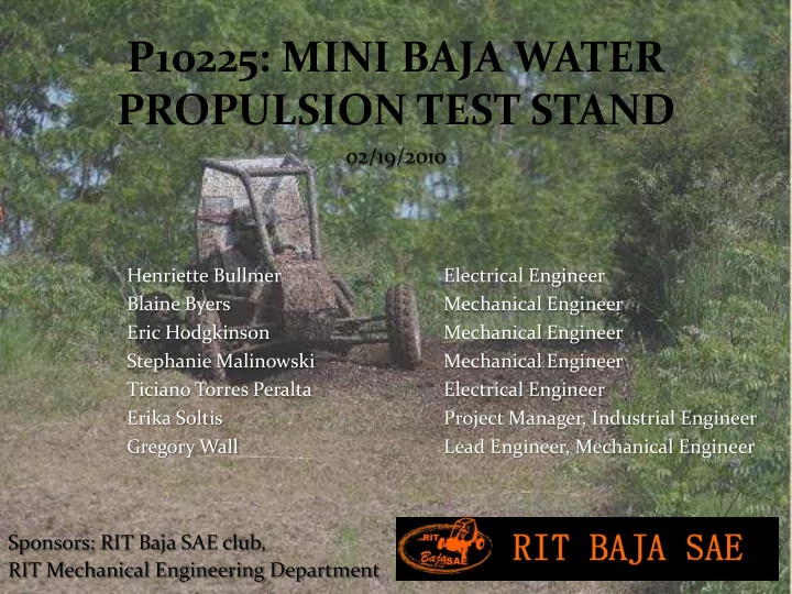

P10225: MINI BAJA WATER PROPULSION TEST STAND 02/19/2010 Henriette Bullmer Electrical Engineer Blaine Byers Mechanical Engineer Eric Hodgkinson Mechanical Engineer Stephanie Malinowski Mechanical Engineer Ticiano Torres Peralta Electrical Engineer Erika Soltis Project Manager, Industrial Engineer Gregory Wall Lead Engineer, Mechanical Engineer Sponsors: RIT Baja SAE club, RIT Mechanical Engineering Department
PROJECT DESCRIPTION Customer: Mini Baja club at RIT Endurance race and water event Project Scope: Usable test stand Software for determining best water propulsion option Documentation supporting this decision
CUSTOMER NEEDS Test stand can produce repeatable tire/fender performance data Software can document results of tests SOP is provided for test stand use Test stand is safe to use Test stand is capable of withstanding brief exposure to rain
ENGINEERING SPECIFICATIONS Specif ifica icati tion on Descrip ipti tion Marginal inal Value Maximum forward propulsion test stand can withstand 13.5 lb Maximum buoyancy force test stand can withstand 55 lb Standard Operating Procedure provided to Baja 1 copy Minimum frame material strength Factor of safety of 2 Maximum water force tank can withstand 6.81 psi Maximum test stand width 4 ft All electronics are resistant to rain water yes
CONCEPT DESCRIPTION Build test stand: Stand available for use at any time Stand designed to meet exact Baja needs Requires little preparation before each test is performed Controls outside variables that could affect results Alternatives: Scale model, Baja vehicle, outside testing, RIT facilities, simulation, rent testing equipment
SYSTEM ARCHITECTURE Load Cell Wheel/Fender Assembly Control Drive Computer Electronics System Legend: Signal Mechanical Motor
DESIGN SUMMARY Sliding assembly pulls against load cell when wheel turns to measure forward propulsion Top assembly supports hanging wheel, slides along top rails as wheel turns Painted Vinyl liner inside plywood steel frame contains water Plywood walls distribute weight of water
SYSTEM TESTING RESULTS Mechanical: Electrical: Liner Material Test LabVIEW Data Acquisition Test Liner Seal Test Hall Sensor Test Lid Seal Test Motor Control Unit Test Weld Inspection Test Signal Isolation Test Frame Loading Test Electronics Wiring Test Lid Placement Test Stand Grounding Test Tank Water-holding Test Data Acquisition Operating System Support Test Rail and Runner Movement Test Shaft Alignment Test Integration: Wheel in Water Test Bearing Load Test Test Stand Assembly Test Bearing Twist Test Complete Mechanical System Structure Natural Frequency Test Movement Test
TEST STAND PICTURES
PROJECT EVALUATION Enthusiastic and supportive customer Customer needs were not firm at start and changed throughout process Assembly went smoothly because of detailed planning and CAD drawings Most of project completed on time with flexible, coordinated team efforts Significant support from experts Liner ended up being more complicated than expected Electronic control of motor wasn’t possible but manual solution was acceptable
RECOMMENDATIONS Run test stand without lid when possible Add a window in the tank and liner to allow for viewing test if lid is used Determine fender designs that don’t create so much friction against the wheel/tire Add more sensors to allow for gathering of more information (torque)
QUESTIONS?
Recommend
More recommend