Optimization of Michelson Interferometer Signals in Crackle Noise - PowerPoint PPT Presentation
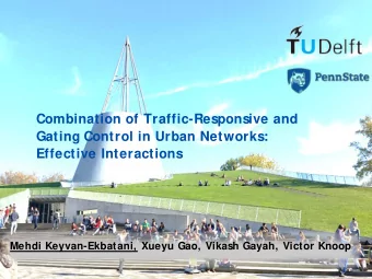
Optimization of Michelson Interferometer Signals in Crackle Noise Detection Horng Sheng Chia, Gabriele Vajente LIGO SURF Project August 20, 2014 Crackle Noise Crackle noise may affect LIGO detection Impulsive release of energy or
Optimization of Michelson Interferometer Signals in Crackle Noise Detection Horng Sheng Chia, Gabriele Vajente LIGO SURF Project August 20, 2014
Crackle Noise • Crackle noise may affect LIGO detection • Impulsive release of energy or acoustic pressure • Changes in geometry • Question: is crackle noise a problem to LIGO? Figure : Dahmen, Benzion, and Uhl, Phys. Rev. Lett. (2009)
Crackle Setup • Output: Difference between symmetric and antisymmetric port readings
Motivation • Crackle experiment is prone to noises: 1. Laser frequency noise 2. Laser intensity noise • Mirror misalignment also affects signal output • Coupling of noises can be minimized by adjusting parameters of setup • Before (Crackle 1 experiment): - trial and error - ideal parameters drift away due to environmental factors • Now (Crackle 2 experiment): - Goal: automatically adjust these parameters to optimize output • Simulation - MIST optical toolbox
Laser Frequency Noise • Variation of laser frequency • Laser Frequency Noise Coupling, g freq = ∆ L/ν • Aim: equalize macroscopic length difference, O(1mm) • Piezo-translation stage controls length of one arm Gain of Frequency Noise Coupled × 10 −18 [m/Hz] 6 Simulation Expected 5 4 3 2 1 0 0 0.5 1 1.5 Macroscopic Length Difference, [mm]
Laser Frequency Noise (Algorithm) − 17 x 10 4 Theoretical Laser frequency noise gain [10 − 17 m/Hz] Iteration Initial Final 3 2 1 0 − 1 0.31 0.315 0.32 0.325 0.33 0.335 0.34 Macroscopic Length of movable arm [m] • 100 measurements with random measurement uncertainties • Average of 5 steps to complete algorithm
Laser Intensity Noise • Variation of laser power • RIN = δP P • Aim: adjust microscopic length difference, O(1 nm) • Strategy: Locking (negative feedback) = ⇒ half fringe condition 3.5 SP AP ABS(SP−AP) 3 2.5 2 Power [W] 1.5 1 0.5 0 −0.5 −4 −3 −2 −1 0 1 2 3 4 Phase of movable arm [rad]
Mirror Misalignment • Effects of misalignment: (i) additional phase added by mirror misalignment (ii) shifted beam center = ⇒ reduced fringe contrast • Aim: align mirrors so fringe contrast is close to unity • Fringe contrast = P max − P min � � P max + P min = Re [ ψ 1 ψ ∗ 2 ] dxdy
Mirror Misalignment (Model) 2 L 2 2 α 2 + k 2 w 2 L 2 α 2 k 2 L 2 2 w 2 α 2 − k 2 w 2 α 2 • � � Re [ ψ r ψ ∗ o ] dxdy = e − − w 2 2 R 2 R 2 • L 2 = length of arm, w = beam radius, k = wavenumber, α = misalignment angle, R = radius of curvature of wavefront 1 Simulation Expected 0.9 0.8 0.7 Fringe contrast 0.6 0.5 0.4 0.3 0.2 0.1 0 −3 −2 −1 0 1 2 3 Angular misalignment of one mirror [mrad]
Gradient Ascent Optimization • Crucial parameter: step size • Divide fringe contrast pattern into approximate linear regimes grad x 1 grad y 1 grad local • δ = δ max grad max , where grad local = grad x 2 grad y 2 IV 1 V III II I Simulation 0.9 (0.256, 0.90) (0.177, 0.95) 0.8 0.7 Fringe contrast 0.6 (0.662, 0.50) 0.5 0.4 0.3 0.2 (1.21, 0.10) 0.1 0 −3 −2 −1 0 1 2 3 Angular misalignment of one mirror [rad] −3 x 10
Alignment Plots 0.7 1 X1 Y1 0.9 X2 0.6 Y2 Angular displacement [mrad] 0.8 0.5 0.7 Fringe Contrast 0.4 0.6 0.3 0.5 0.4 0.2 0.3 0.1 0.2 0 0.1 −0.1 0 0 5 10 15 20 25 30 35 0 5 10 15 20 25 Steps Steps
Conclusion • All 3 algorithms have been tested rigorously • Next step: implement in real crackle experiment • Acknowledge: Gabriele Vajente, Xiaoyue Ni, Alan Weinstein, LIGO SURF students, NSF • Thank You!
Alignment Plots 1 1 X1 Y1 0.9 X2 0.8 Y2 Angular displacement [m rad] 0.8 0.6 0.7 Fringe Contrast 0.6 0.4 0.5 0.2 0.4 0.3 0 0.2 −0.2 0.1 −0.4 0 0 5 10 15 20 25 0 5 10 15 20 25 Steps Steps
Recommend


More recommend
Explore More Topics
Stay informed with curated content and fresh updates.