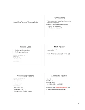
Optimal Service Placement using Pseudo Service Chaining Mechanism - PowerPoint PPT Presentation
IETF 97 meeting @ Seoul Optimal Service Placement using Pseudo Service Chaining Mechanism 2016. 11. 15. Taeheum Na {taeheum@etri.re.kr} Network SW Platform Research Section ETRI Contents Background NFV Environment Related work
IETF 97 meeting @ Seoul Optimal Service Placement using Pseudo Service Chaining Mechanism 2016. 11. 15. Taeheum Na {taeheum@etri.re.kr} Network SW Platform Research Section ETRI
Contents Background • NFV Environment • Related work Pseudo Service Chaining Mechanism • Phase 1: Calculation of virtual link cost • Phase 2: Selection of available computing nodes • Phase 3: Greedy placement Conclusion - 1 -
Background - 2 -
Our NFV Envir ironment Playnet? = Playground of NFV Environment • Open Source MANO (OSM) based NFV Environment • Playstore concept UI/UX • Extended VIM functionality OpenStack (liberty) Container and KVM based virtualization VNFM NFVO Using Nova-docker plugin Consideration for point-to-point link (E-line type) EM EM VIM • Saving & loading Network Service (NS) VNF VNF VIM API Save and load NS using VNFFG format When NS is loaded, need to consider optimal placement VIM NFVI Openstack (Openstack) (Openstack) API Link VIM Server Function - 3 -
Rela lated work ETSI Standard • VNFFG Descriptor (vnffgd) Reference type – VLD • Virtual Link Descriptor (vld) Id, vendor, # of endpoints Requirement Root requirement – BW of E-line, root bandwidth of E-Tree or E-LAN Leaf requirement – throughput requirement of leaf connection (Tree, LAN) QoS • Virtual Link Record (vlr) Same Requirement to VLD Allocated_capacity – bandwidth allocated for each of the QoS • need more specific parameter for the link - 4 -
Rela lated work IETF Standard • draft-irtf-nfvrg-resource-management-service-chain-03 4. Use case 4.4 Traffic optimization – For efficiency of resource usage, the NFP instances need to be built by default to localize the traffic flows • draft-lee-sfc-dynamic-instantiation-01 3. SFC dynamic instantiation Traffic optimization: construct or maintain SFPs to localize the traffic in the network considering load and administrative domains of SFIs and SFLs • Our work can be one of the use case in draft document - 5 -
Rela lated work OpenStack – Filter Scheduler • Step 1: Filtering Filtering compute node based on available virtual resources • Step 2: Weighting Ram, I/O operation weight multiplier Multiplier can be configured • Step 3: Sorting Largest weighted node have highest priority - 6 -
Pseudo Service Chaining Mechanism - 7 -
Pseudo Servic ice Chain inin ing Mechanis ism Goal • By localizing SFs (=Minimize the number of entity in SFPs) based on link description metric • Saving core network bandwidth • By avoiding capsulation, save the computation resource • Getting more better performance of virtual link Assumption • Doesn't consider scaling, failover and policy • Metric of Link parameter is decided by Operator (SFC user) at first • Based on monitoring, it can be updated - 8 -
Pseudo Servic ice Chain inin ing Mechanis ism Overview of placement • Phase 1: Calculation of Virtual Link Costs based on VLD parameters calculate link cost Selecting pseudo virtual node (PVN) • Phase 2: selection of available computing nodes • Phase 3: Placement PVN • It is recursively conducted - 9 -
Pseudo Servic ice Chain inin ing Mechanis ism Phase 1: Calculation of Virtual Link Costs • Transaction among service nodes • Transaction weight at virtual link • Volume of traffic at virtual link Table 1. Parameter definitions for calculation of virtual link costs. Notation Definition Amount of transactions at a virtual link i Transaction weight for a virtual link i Volume of traffic at a virtual link i Cost of a virtual link i List of virtual links in the order of cost - 10 -
Pseudo Servic ice Chain inin ing Mechanis ism Phase 2: Selection of available computing nodes • Based on resource requirement of instance • Available compute node 1 st available compute node Available resource > resource requirement of PVN 2 nd Available compute node Available resource > minimum resource requirement of SN • Sort in descending order - 11 -
Pseudo Servic ice Chain inin ing Mechanis ism Phase 3: Greedy placement • Multiple-Knapsack Problem 𝑦 𝑘𝑙 1, 𝑗𝑔 𝑤𝑛 𝑘 𝑗𝑡 𝑏𝑡𝑡𝑗𝑜𝑓𝑒 𝑗𝑜 𝑞𝑤𝑛 𝑙 (5) 0, 𝑝𝑢ℎ𝑓𝑠𝑥𝑗𝑡𝑓 𝑜 𝑊𝑠 𝑘 𝑦 𝑘𝑙 < 𝑆 𝑗 (6) 𝑘 =1 𝑜 𝑞𝑥 𝑙 = 𝑥 𝑘 𝑦 𝑘𝑙 (7) 𝑘 =1 𝑧 𝑗𝑙 1, 𝑗𝑔 𝑞𝑤𝑛 𝑙 𝑗𝑡 𝑏𝑡𝑡𝑗𝑜𝑓𝑒 𝑗𝑜 𝐵𝑂 𝑗 (8) 0, 𝑝𝑢ℎ𝑓𝑠𝑥𝑗𝑡𝑓 𝑛 𝑜 𝑛𝑏𝑦𝑗𝑛𝑗𝑨𝑓𝑡 𝑨 = 𝑞𝑥 𝑙 𝑧 𝑗𝑙 (9) 𝑗 =1 𝑘 =1 - 12 -
Pseudo Servic ice Chain inin ing Mechanis ism Phase 3: Greedy placement • Maximize the sum of cost in the allocated PVM 𝒖 𝟑 > 𝒖 𝟐 > 𝒖 𝟒 𝒏𝒃𝒚( 𝒖 𝟐 , 𝒖 𝟒 ) = 𝒖 𝟐 𝑻𝑶 𝟓 𝑸𝑾𝑶 𝟐 𝑻𝑶 𝟐 𝑺 𝟓 𝑺 𝟑 +𝑺 𝟒 𝑺 𝟐 𝒖 𝟑 > 𝒖 𝟐 > 𝒖 𝟒 𝒖 𝟐 𝒋𝒈, 𝑩𝑺 𝟑 > 𝑺 𝟑 +𝑺 𝟒 𝒖 𝟑 𝒖 𝟒 𝑻𝑶 𝟑 𝑻𝑶 𝟓 𝑻𝑶 𝟒 𝑩𝑶 𝟑 𝑩𝑺 𝟑 < 𝑺 𝟐 + 𝑺 𝟑 +𝑺 𝟒 𝑺 𝟑 𝑺 𝟓 𝑻𝑶 𝟐 𝑺 𝟒 𝑩𝑶 𝟐 𝑩𝑺 𝟑 −(𝑺 𝟑 +𝑺 𝟒 ) 𝑩𝑶 𝟒 𝑺 𝟐 𝑩𝑺 𝟐 𝑩𝑺 𝟒 𝑩𝑺 𝟑 > 𝑩𝑺 𝟐 > 𝑩𝑺 𝟒 𝑩𝑶 𝟑 𝑩𝑶 𝟐 𝑩𝑺 𝟑 𝑩𝑶 𝟒 𝒋𝒈, 𝑩𝑺 𝟑 > 𝑺 𝟑 +𝑺 𝟒 𝒖 𝟒 𝑻𝑶 𝟓 𝒖 𝟐 𝑩𝑺 𝟐 𝑩𝑺 𝟒 𝑻𝑶 𝟐 𝑸𝑾𝑶 𝟐 𝑺 𝟓 𝑺 𝟐 𝑺 𝟑 +𝑺 𝟒 𝒖 𝟑 > 𝒖 𝟐 > 𝒖 𝟒 𝑩𝑺 𝟑 > 𝑩𝑺 𝟐 > 𝑩𝑺 𝟒 𝑩𝑶 𝟑 𝑩𝑶 𝟐 𝑩𝑺 𝟑 𝑩𝑶 𝟒 𝑩𝑺 𝟐 𝑩𝑺 𝟒 𝑩𝑺 𝟑 > 𝑩𝑺 𝟐 > 𝑩𝑺 𝟒
Pseudo Servic ice Chain inin ing Mechanis ism Recursive operation • Compare minimum resource requirement 𝒖 𝟐 𝒖 𝟑 𝒖 𝟒 𝒖 𝟒 𝑻𝑶 𝟑 𝑻𝑶 𝟓 𝑻𝑶 𝟓 𝑻𝑶 𝟒 𝒖 𝟐 𝑻𝑶 𝟐 𝑸𝑾𝑶 𝟐 𝑺 𝟑 𝑻𝑶 𝟐 𝑺 𝟓 𝑺 𝟓 𝑺 𝟒 𝑺 𝟐 𝑺 𝟑 +𝑺 𝟑 𝑺 𝟐 𝒖 𝟑 > 𝒖 𝟐 > 𝒖 𝟒 𝒖 𝟑 > 𝒖 𝟐 > 𝒖 𝟒 𝒋𝒈, 𝑩𝑺 𝟑 > (𝑺 𝟑 +𝑺 𝟒 ) 𝑩𝑶 𝟑 𝑩𝑶 𝟑 𝑩𝑺 𝟑 𝑩𝑺 𝟑 𝑩𝑶 𝟐 𝑩𝑶 𝟐 𝑩𝑶 𝟒 𝑩𝑶 𝟒 𝑩𝑺 𝟐 𝑩𝑺 𝟐 𝑩𝑺 𝟒 𝑩𝑺 𝟒 𝑩𝑺 𝟑 > 𝑩𝑺 𝟐 > 𝑩𝑺 𝟒 𝑩𝑺 𝟑 > 𝑩𝑺 𝟐 > 𝑩𝑺 𝟒 𝒏𝒃𝒚( 𝒖 𝟐 , 𝒖 𝟒 ) = 𝒖 𝟐 𝑻𝑶 𝟓 𝒏𝒃𝒚( 𝒖 𝟐 , 𝒖 𝟒 ) = 𝒖 𝟐 𝑻𝑶 𝟓 𝑻𝑶 𝟐 𝑻𝑶 𝟐 𝑺 𝟓 𝑺 𝟓 𝑺 𝟐 𝑺 𝟐 𝒖 𝟐 > 𝒖 𝟒 𝒖 𝟐 > 𝒖 𝟒 𝑩𝑶 𝟑 𝑩𝑶 𝟑 𝑩𝑺 𝟑 −(𝑺 𝟑 +𝑺 𝟑 ) 𝑩𝑶 𝟐 𝑩𝑶 𝟒 𝑩𝑺 𝟑 −(𝑺 𝟑 +𝑺 𝟒 ) 𝑩𝑶 𝟐 𝑩𝑶 𝟒 𝑩𝑺 𝟐 𝑩𝑺 𝟒 𝑩𝑺 𝟐 𝑩𝑺 𝟒 𝑩𝑺 𝟐 > 𝑩𝑺 𝟒 > 𝑩𝑺 𝟑 −(𝑺 𝟑 +𝑺 𝟒 ) 𝑩𝑺 𝟐 > 𝑩𝑺 𝟒 > 𝑩𝑺 𝟑 −(𝑺 𝟑 +𝑺 𝟒 ) - 14 -
Conclu lusion Result • Better performance for Loss-rate of UDP • Decrease round trip time • Less CPU usage of host node(Interrupt) - 15 -
Questio ion? taeheum@etri.re.kr - 16 -
Recommend


More recommend
Explore More Topics
Stay informed with curated content and fresh updates.