One-Port v Admittance Parameters Network - Hybrid Parameters i' - - PowerPoint PPT Presentation

one port
SMART_READER_LITE
LIVE PREVIEW

One-Port v Admittance Parameters Network - Hybrid Parameters i' - - PowerPoint PPT Presentation

Two-Port Networks One-Port Networks Definitions i 1 + Impedance Parameters One-Port v Admittance Parameters Network - Hybrid Parameters i' 1 Transmission Parameters A pair of terminals at which a signal (voltage or


slide-1
SLIDE 1

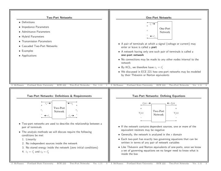
Two-Port Networks: Definitions & Requirements Two-Port Network

v1

  • +

i1 i'1

  • +

i2 i'2 v2

  • Two-port networks are used to describe the relationship between a

pair of terminals

  • The analysis methods we will discuss require the following

conditions be met

  • 1. Linearity
  • 2. No independent sources inside the network
  • 3. No stored energy inside the network (zero initial conditions)
  • 4. i1 = i′

1 and i2 = i′ 2

  • J. McNames

Portland State University ECE 222 Two-Port Networks

  • Ver. 1.11

3

Two-Port Networks

  • Definitions
  • Impedance Parameters
  • Admittance Parameters
  • Hybrid Parameters
  • Transmission Parameters
  • Cascaded Two-Port Networks
  • Examples
  • Applications
  • J. McNames

Portland State University ECE 222 Two-Port Networks

  • Ver. 1.11

1

Two-Port Networks: Defining Equations Two-Port Network

V1(s)

  • +
  • +

V2(s) I1(s) I2(s)

  • If the network contains dependent sources, one or more of the

equivalent resistors may be negative

  • Generally, the network is analyzed in the s domain
  • Each two-port has exactly two governing equations that can be

written in terms of any pair of network variables

  • Like Th´

evenin and Norton equivalents of one-ports, once we know a set of governing equations we no longer need to know what is inside the box

  • J. McNames

Portland State University ECE 222 Two-Port Networks

  • Ver. 1.11

4

One-Port Networks One-Port Network

v

  • +

i1 i'1

  • A pair of terminals at which a signal (voltage or current) may

enter or leave is called a port

  • A network having only one such pair of terminals is called a
  • ne-port network
  • No connections may be made to any other nodes internal to the

network

  • By KCL, we therefore have i1 = i′

1

  • We discussed in ECE 221 how one-port networks may be modeled

by their Th´ evenin or Norton equivalents

  • J. McNames

Portland State University ECE 222 Two-Port Networks

  • Ver. 1.11

2

slide-2
SLIDE 2

Impedance Parameter Measurements Continued Two-Port Network

  • +

V2(s) V1(s)

  • +

I2(s)

V1 = z11I1 + z12I2 V2 = z21I1 + z22I2 If the left port is an open circuit (I1 = 0), then we can easily solve for the other two impedance parameters: z12 = V1 I2

  • I1=0

z22 = V2 I2

  • I1=0
  • J. McNames

Portland State University ECE 222 Two-Port Networks

  • Ver. 1.11

7

Impedance Parameters Two-Port Network

I1(s)

  • +

V2(s) V1(s)

  • +

I2(s)

V1 = z11I1 + z12I2 V2 = z21I1 + z22I2

  • V1

V2

  • =
  • z11

z12 z21 z22 I1 I2

  • Suppose the currents and voltages can be measured
  • Alternatively, if the circuit in the box is known, V1 and V2 can be

calculated based on circuit analysis

  • Relationship can be written in terms of the impedance parameters
  • We can also calculate the impedance parameters after making two

sets of measurements

  • J. McNames

Portland State University ECE 222 Two-Port Networks

  • Ver. 1.11

5

Impedance Parameter Measurements Summarized Two-Port Network

I1(s)

  • +

V2(s) V1(s)

  • +

I2(s)

z11 = V1 I1

  • I2=0

z12 = V1 I2

  • I1=0

z21 = V2 I1

  • I2=0

z22 = V2 I2

  • I1=0
  • J. McNames

Portland State University ECE 222 Two-Port Networks

  • Ver. 1.11

8

Impedance Parameter Measurements Two-Port Network

I1(s)

  • +

V2(s) V1(s)

  • +

V1 = z11I1 + z12I2 V2 = z21I1 + z22I2 If the right port is an open circuit (I2 = 0), then we can easily solve for two of the impedance parameters: z11 = V1 I1

  • I2=0

z21 = V2 I1

  • I2=0
  • J. McNames

Portland State University ECE 222 Two-Port Networks

  • Ver. 1.11

6

slide-3
SLIDE 3

Example 1: Workspace

  • J. McNames

Portland State University ECE 222 Two-Port Networks

  • Ver. 1.11

11

Impedance Parameter Equivalent

z11 z22 z12I2 z21I1 V1(s)

  • +

I1(s)

  • +

V2(s) I2(s)

V1 = z11I1 + z12I2 V2 = z21I1 + z22I2

  • Once we know what the impedance parameters are, we can model

the behavior of the two-port with an equivalent circuit.

  • Notice the similarity to Th´

evenin and Norton equivalents

  • J. McNames

Portland State University ECE 222 Two-Port Networks

  • Ver. 1.11

9

Example 2: Parameter Conversion Two-Port Network

V1(s)

  • +
  • +

V2(s) I1(s) I2(s)

V1 = z11I1 + z12I2 V2 = z21I1 + z22I2 In general, the two defining equations can be written in terms of any pair of variables. For example, rewrite the defining equations in terms

  • f the voltages V1 and V2.
  • J. McNames

Portland State University ECE 222 Two-Port Networks

  • Ver. 1.11

12

Example 1: Impedance Parameters

V1

  • +

V2

  • +

I1 I2

40 Ω 200 Ω 500 Ω 800 Ω 1 kΩ

Find the z parameters of the circuit.

  • J. McNames

Portland State University ECE 222 Two-Port Networks

  • Ver. 1.11

10

slide-4
SLIDE 4

Impedance & Admittance Parameters Two-Port Network

V1(s)

  • +
  • +

V2(s) I1(s) I2(s)

Impedance Parameters V1 = z11I1 + z12I2 V2 = z21I1 + z22I2

  • V1

V2

  • =
  • z11

z12 z21 z22 I1 I2

  • Admittance Parameters

I1 = y11V1 + y12V2 I2 = y21V1 + y22V2

  • I1

I2

  • =
  • y11

y12 y21 y22 V1 V2

  • J. McNames

Portland State University ECE 222 Two-Port Networks

  • Ver. 1.11

15

Example 2: Workspace

  • J. McNames

Portland State University ECE 222 Two-Port Networks

  • Ver. 1.11

13

Hybrid Parameters Two-Port Network

V1(s)

  • +
  • +

V2(s) I1(s) I2(s)

Hybrid Parameters V1 = h11I1 + h12V2 I2 = h21I1 + h22V2 V1 I2

  • =

h11 h12 h21 h22 I1 V2

  • Inverse Hybrid Parameters

I1 = g11V1 + g12I2 V2 = g21V1 + g22I2 I1 V2

  • =

g11 g12 g21 g22 V1 I2

  • J. McNames

Portland State University ECE 222 Two-Port Networks

  • Ver. 1.11

16

Example 2: Workspace Continued

  • J. McNames

Portland State University ECE 222 Two-Port Networks

  • Ver. 1.11

14

slide-5
SLIDE 5

Example 3: Two-Port Measurements The following measurements were taken from a two-port network. Find the transmission parameters. Port 2 Open V1 = 150 cos(4000t) V applied I1 = 25 cos(4000t − 45◦) A measured V2 = 1000 cos(4000t + 15◦) V measured Port 2 Shorted V1 = 30 cos(4000t) V applied I1 = 1.5 cos(4000t + 30◦) A measured I2 = 0.25 cos(4000t + 150◦) A measured

  • J. McNames

Portland State University ECE 222 Two-Port Networks

  • Ver. 1.11

19

Transmission Parameters Two-Port Network

V1(s)

  • +
  • +

V2(s) I1(s) I2(s)

Transmission Parameters V1 = a11V2 − a12I2 I1 = a21V2 − a22I2 V1 I1

  • =

a11 b12 a21 a22 V2 −I2

  • = A
  • V2

−I2

  • Inverse Transmission Parameters

V2 = b11V1 − b12I1 I2 = b21V1 − b22I1 V2 I2

  • =

b11 b12 b21 b22 V1 −I1

  • = B
  • V2

−I2

  • J. McNames

Portland State University ECE 222 Two-Port Networks

  • Ver. 1.11

17

Example 3: Workspace

  • J. McNames

Portland State University ECE 222 Two-Port Networks

  • Ver. 1.11

20

Transmission Parameter Conversion Two-Port Network

V1(s)

  • +
  • +

V2(s) I1(s) I2(s)

  • Altogether there are 6 sets of parameters
  • Each set completely describes the two-port network
  • Any set of parameters can be converted to any other set
  • We have seen one example of a conversion
  • A complete table of conversions is listed in the text (Pg. 933)
  • You should have a copy of this in your notes for the final
  • J. McNames

Portland State University ECE 222 Two-Port Networks

  • Ver. 1.11

18

slide-6
SLIDE 6

Example 4: Workspace Continued

  • J. McNames

Portland State University ECE 222 Two-Port Networks

  • Ver. 1.11

23

Example 4: Two-Port Analysis

v1

  • +

i1 16.2 v3 v3

  • +

v2

  • +

i2

40 Ω 160 Ω 200 Ω 800 Ω

Find the hybrid parameters for the circuit shown above.

  • J. McNames

Portland State University ECE 222 Two-Port Networks

  • Ver. 1.11

21

Example 5: Two-Port Measurements The following measurements were taken from a two-port network. Find the transmission parameters. Port 1 Open V1 = 1 mV V2 = 10 V I2 = 200 µA Port 1 Shorted I1 = −0.5 µA I2 = 80 µA V2 = 5 V Hint: △b = b11b22 − b12b21, a11 = b22

△b , a12 = b12 △b , a21 = b21 △b , and

a22 = b11

△b .

  • J. McNames

Portland State University ECE 222 Two-Port Networks

  • Ver. 1.11

24

Example 4: Workspace

v1

  • +

i1 16.2 v3 v3

  • +

v2

  • +

i2

40 Ω 160 Ω 200 Ω 800 Ω

  • J. McNames

Portland State University ECE 222 Two-Port Networks

  • Ver. 1.11

22

slide-7
SLIDE 7

Example 6: Workspace

R1 v1(t) v2(t)

  • +

R3 R4 R2 C2 C1 v+(t) v-(t) i1 i2

  • J. McNames

Portland State University ECE 222 Two-Port Networks

  • Ver. 1.11

27

Example 5: Workspace

  • J. McNames

Portland State University ECE 222 Two-Port Networks

  • Ver. 1.11

25

Example 6: Workspace Continued (1)

R1 v1(t) v2(t)

  • +

R3 R4 R2 C2 C1 v+(t) v-(t) i1 i2

  • J. McNames

Portland State University ECE 222 Two-Port Networks

  • Ver. 1.11

28

Example 6: Two-Port Analysis

R1 v1(t) v2(t)

  • +

R3 R4 R2 C2 C1 v+(t) v-(t) i1 i2

Find an expression for the transfer function, h11, z11, g12, g22, a11, and y21.

  • J. McNames

Portland State University ECE 222 Two-Port Networks

  • Ver. 1.11

26

slide-8
SLIDE 8

Cascaded Two-Port Networks Two Port Network A

V1(s)

  • +
  • +

V2A(s) I1(s) I2A(s)

Two Port Network B

V1B(s)

  • +
  • +

V2(s) I1B(s) I2(s)

V1

I1

  • =
a11

a12 a21 a22

  • A
  • V2A

−I2A

  • V1B

I1B

  • =
a11

a12 a21 a22

  • B
  • V2

−I2

  • V2A

−I2A

  • =
V1B

I1B

  • V1

I1

  • =
a11

a12 a21 a22

  • A
a11

a12 a21 a22

  • B
  • V2

−I2

  • J. McNames

Portland State University ECE 222 Two-Port Networks

  • Ver. 1.11

31

Example 6: Workspace Continued (2)

R1 v1(t) v2(t)

  • +

R3 R4 R2 C2 C1 v+(t) v-(t) i1 i2

  • J. McNames

Portland State University ECE 222 Two-Port Networks

  • Ver. 1.11

29

Cascaded Two-Port Networks Continued Two Port Network A

V1(s)

  • +
  • +

V2A(s) I1(s) I2A(s)

Two Port Network B

V1B(s)

  • +
  • +

V2(s) I1B(s) I2(s)

The inverse transmission parameters are also convenient for cascaded networks.

V2

I2

  • =
b11

b12 b21 b22

  • A
  • V1B

−I1B

  • V2A

I2A

  • =
b11

b12 b21 b22

  • B
  • V1

−I1

  • V1B

−I1B

  • =
V2A

I2A

  • V2

I2

  • =
b11

b12 b21 b22

  • A
b11

b12 b21 b22

  • B
V1

−I1

  • J. McNames

Portland State University ECE 222 Two-Port Networks

  • Ver. 1.11

32

Cascaded Two-Port Networks Two Port Network A

V1(s)

  • +
  • +

V2A(s) I1(s) I2A(s)

Two Port Network B

V1B(s)

  • +
  • +

V2(s) I1B(s) I2(s)

  • Two networks are cascaded when the output of one is the input
  • f the other
  • Note that V2A = V1B and −I2A = I1B
  • The transmission parameters take advantage of these properties
  • J. McNames

Portland State University ECE 222 Two-Port Networks

  • Ver. 1.11

30

slide-9
SLIDE 9

Cascaded Systems: Two-Port Networks versus H(s) Two Port Network A

V1(s)

  • +
  • +

V2A(s) I1(s) I2A(s)

Two Port Network B

V1B(s)

  • +
  • +

V2(s) I1B(s) I2(s)

  • Two-ports and transfer functions H(s) are closely related
  • H(s) only relates the input signal to the output signal
  • Two-ports relate both voltages and currents at each port
  • You cannot cascade H(s) unless the circuits are active
  • Two-port networks have no such restriction
  • Two-ports are used to design passive filters
  • However, two-ports are more complicated than H(s)
  • J. McNames

Portland State University ECE 222 Two-Port Networks

  • Ver. 1.11

33