Objectives Buffer insertion Transistor and gate sizing Static - PowerPoint PPT Presentation
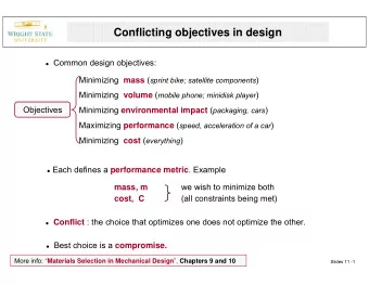
Objectives Buffer insertion Transistor and gate sizing Static timing analysis Interconnect system order reduction Lower power design High level synthesis Design for manufacture Performance bound evaluation
• Objectives – Buffer insertion – Transistor and gate sizing – Static timing analysis – Interconnect system order reduction – Lower power design – High level synthesis – Design for manufacture – Performance bound evaluation
• What we have previously discussed are the normal, basic topics. • There are certain issues in each design stage which need special attention in order to fulfill the potential of available technology. • These advanced issues usually are related to the performance requirement and upcoming process technology. • Most subjects discussed here are currently active research areas.
• Understanding these issues requires an in-depth discussion of specific topics in circuits and systems, optimization theory and IC manufacture process. • In the following we will explore these issues with the purpose of revealing their implications in the perspective of circuits and systems. – focus on the relevance in relation to IC design. – only outline ideas in these state of the art methods in order to avoid getting into the complex physics and algorithms. – use examples to illustrate the key concepts and results. • The reader can find more detailed discussions from the references list in this chapter.
• Buffer insertion has been mentioned everywhere in VLSI design. – For instance, in clock network layout, buffer insertion has been used to balance the clock skew. – The mechanism behind buffer insertion’s ability to reduce the interconnect delay has not been well explained in a simple and intuitive way. – We will employ a simple example to demonstrate how and why.
• How does buffer insertion reduce interconnect delay and save power?
• Before buffer insertion
• After buffer insertion
• Although timing optimization has always been critical in the design process, present day design techniques and process technologies are making noise analysis and avoidance just as important, or in some cases even more important, than timing analysis and optimization. • The shrinking of minimum distance between adjacent wires has caused an increase in the coupling capacitance of a net to its neighbors. • Furthermore, a wire’s thickness is typically greater than its width, increasing the ratio of coupling to total capacitance. • A large coupling capacitance can cause a switching net to induce significant noise onto a neighboring net, resulting in an incorrect functional response.
• How does buffer insertion reduce crosstalk?
• Transistor and gate sizing has been widely used to optimize the circuit performance in terms of speed and power consumption. – Low power designs need to have minimum sized transistors. The channel length is reduced to a degree where velocity saturation occurs, changing first-order MOS equations. – Parasitic capacitances become more important. – Maintaining strong charge or discharge currents is essential for high speed operation. – Considering these facts, transistor sizes can be increased while lowering the supply voltages, resulting in reduced total power dissipation and faster circuit speed.
• Buffer sizing
• Size ratio
• The reason for variable size ratio – Figure 7 ‑ 8 Input stew rate affects its delay – The slew rate of the next stage is getting slower if the fixed size ration is used
• Most combinational logic gates can be modeled as a simple inverter when evaluating circuit property. – For instance, the electric property, when two p -transistors in a NOR gate are turn-on, is similar to when the p - transistor of an inverter is turn-on. – We can introduce an “equivalent” size ratio in the inverter to estimate I ds of two p -transistors in NOR (Figure 7 ‑ 9). • The associated capacitance between two gates can also be easily derived. • The same claim can be made for the case when two n - transistors are turn-on.
• Similar to buffer sizing, the transistor size in a gate can also be optimized for low power and satisfactory speed. • The speed (measured by delay) and power consumption of a gate, in a general combinational logic block, has the following relationship shown in Figure 7 ‑ 10. • If the design spec requires a delay d2 > d1 , it doesn’t make sense to put in a gate with delay d1 since it will consume much more power p1 > p2 .
• In real designs, there are many paths in the combinational logics containing different delays. – There is a great opportunity to optimize the transistor size to make the delay as even as possible, assuming all of them satisfy the requirement posted by the clock period. – It has been shown that more than 30% power consumption can be achieved by such a transistor sizing method.
• Generally, gate sizing is a nonlinear optimization problem and obtaining the global optimal is difficult. – Most CAD tools introduce some degree of assumption to make the objective function a convex one. Thus, the optimum solution can be found. – Real design data show that most of the time the results produced by such CAD tools are very good, though no one knows the real optimum solution.
• High-performance integrated circuits have traditionally been characterized by the clock frequency at which they operate. • Gauging the ability of a circuit to operate at the specified speed requires ability to measure its delay at numerous steps during the design process. • There are mainly two approaches for timing analysis: static and dynamic timing analysis.
• Static Timing Analysis – Static timing analysis (STA) is a method of computing the expected timing of a digital circuit without requiring circuit level simulation. – By giving each circuit component an “associated delay”, it doesn’t need to test all possible input vectors. – In this way, it treats circuit component delay independently rather than considering them dependently as a solution of a whole system, usually described by a set of ODEs. • STA therefore greatly reduces the time to compute the delay at the expense of accuracy. – On the contrary, dynamic timing analysis uses the circuit simulation, solves ODEs numerically, and tries on large samples of input vectors. Therefore, it is time consuming.
• Critical path – The critical path is defined as the path between an input and an output with the maximum delay. – Once the circuit timing has been computed by one of the techniques below, the critical path can easily be found by using a trace back method.
• Method to calculate the critical path – The delay of a path is the sum of the delays of the interconnects and gates in the path. – This problem can be modeled as to find the max/min path in a graph and can be computed efficiently. – Figure 7 ‑ 12 illustrates how to find the critical path delay of the example in Figure 7 ‑ 11 using STA. – Each gate is considered as an edge with its delay as the weight, and each interconnect is considered as a vertex in a graph. – The algorithm is simply to find the longest/shortest path from the start point to the end point. – This can be done efficiently based on the existing graph theory.
• An example
• Timing analysis is an integral part of ASIC/VLSI design flow. – It has to be accomplished and the functionality of the design must be cleared before the design is subjected to STA. – Anything else can be compromised but not timing! • In addition to the above discussed STA, dynamic timing analysis (DTA) can be used to verify functionality of the design by applying input vectors and checking for correct output vectors. • In contrast, STA checks static delay requirements of the circuit without any input or output vectors.
• Dynamic timing analysis is a circuit level simulation used for the characterization of timing properties of a complete cell, which most of the time is a logic gate. • Dynamic timing analysis and STA are not alternatives to each other. The quality of the DTA increases with the increase of input test vectors. Increased test vectors increase simulation time. • DTA can be used for synchronous as well as asynchronous designs. STA can’t run on asynchronous deigns and therefore DTA is the best way to analyze asynchronous designs. • It is the best suited for designs having clocks crossing multiple domains. • Finally, DTA is also carried out on post layout netlist to verify that functionality of the design has not changed. Test vectors remain same for both.
• Lumped RC vs. Distributed RLC Model
• The reason for a distributed model – The lumped RC needs to be replaced by distributed RLC model when the wavelength of the signal is comparable to the interconnect length. • Any signal can be expanded into Fourier series of which we need to keep several terms that contain the major energy portion. • If the wavelength in the kept terms are comparable to the interconnect wire length, the voltage along interconnect cannot be approximated as a constant.
Recommend


More recommend
Explore More Topics
Stay informed with curated content and fresh updates.