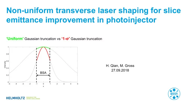

Non-uniform transverse laser shaping for slice emittance improvement in photoinjector ‘Uniform’ Gaussian truncation vs ‘1 - σ’ Gaussian truncation H. Qian, M. Gross 27.09.2018 BSA
Outline Motivation Beam dynamics simulation Transverse laser shaping modification at PITZ Slice emittance measurement for space charge beam Summary Page 2
‘Uniform’ Gaussian truncation vs ‘1 - σ’ Gaussian truncation LCLS-I injector example 2012 , LCLS experience: (prst ab 15, 090701) Fixed BSA • 150 pC, ~1.3 ps (rms) laser Vary laser rms size • Unifrom 1.1- σ Gaussian truncation Pancake emission regime z/x=0.1 transverse transverse uniform truncated Gaussian Gaussian 1σ Gaussian truncation Uniform Comparison of ~25% reduction transverse space charge linearization Experiment: projected emittance Simulated slice emittance Page 3
‘Uniform’ Gaussian truncation vs ‘1 - σ’ Gaussian truncation PITZ/FLASH experience 2010 , Marc Hänel, PHD thesis (PITZ), 1 nC, 20 ps laser 2013 , Tim Plath, Master thesis (FLASH), 20 pC, 1 ps laser PITZ Simulation (gun + drift) FLASH 20 pC experiment 0.75- σ truncation 0.7~0.6- σ truncation Uniform distribution Page 4
‘Uniform’ Gaussian truncation vs ‘1 - σ’ Gaussian truncation Beyond ‘pancake’ photoemission Three photoemission regimes Longitudinal axis z • LCLS-I: ~3 GHz, ~115 MV/m • PITZ: ~1.3 GHz, ~60 MV/m Transverse • LCLS-II: ~0.187 GHz, ~20 MV/m x LCLS-I PITZ LCLS-II z/x <<1 z/x~1 z/x >>1 Space charge force linearization ‘pancake’ ‘cigar’ ‘Pancake’ z/x~0.1 z/x~1 ‘Cigar’ z/x~10 Page 5
Why ‘1 - σ’ Gaussian truncation Analytical prediction A special parabolic radial distribution can linearize transverse space charge to the 3 rd order • 2013 , T. Rao and D. Dowell, An engineering guide to photo injectors Truncation at 0.8 sigma Truncation at 0.9 sigma Truncation at 1.0 sigma z/x~1 Page 6
‘Uniform’ Gaussian truncation vs ‘1 - σ’ Gaussian truncation PITZ injector full simulation Slice emittance Temporal Gaussian laser (19 ps) Temporal flattop laser (22 ps) Gaussian Flattop 0.5 nC Uniform 0.38 0.36 Truncated Gaussian 0.28 0.26 reduction -0.24 -0.28 0.5 nC -24% Gaussian Flattop 1.0 nC Uniform 0.6 0.59 -28% Truncated Gaussian 0.4 0.4 reduction -0.32 -0.32 Proj. emittance Gaussian Flattop 0.5 nC Uniform 0.7 0.4 Truncated Gaussian 0.58 0.31 reduction -0.17 -0.23 1.0 nC -32% Gaussian Flattop 1.0 nC -32% Uniform 1.1 0.65 Truncated Gaussian 0.87 0.46 reduction -0.21 -0.29 Page 7
Imaging from Laser to BSA (Current Setup: Telescope with M = 10) Baseline ZEMAX simulation results • For varying bunch charge (ray tracing) and further optimization need variable laser spot size on cathode (current PITZ setup is fixed to FWHM 3 mm on BSA) Laser BSA output • Simulation results: • Image quality: RMS spot radius of on-axis and off- axis beams • Magnification (ratio of image size to object size |IMA/OBJ| for off-axis beam) Page 8
Requirement: Zoom Range of Telescope (Magnification M) Specifications for truncated Gaussian and THz experiments • Looking for charge range of 20 pC to 2 nC (emittance characterization at PITZ) minimal BSA size (=2 of laser distribution): is 0.8 mm M = 3.3 M min = 2.5 (with safety margin) • maximal BSA size used: 3mm M = 10, but: • • For THz experiments: telescope magnification of M max = 20 would be helpful • Then the laser FWHM size is about 6 mm and the photocathode is fully illuminated • Additional conditions: • For later experiments with “green photocathodes”: Check performance for 515 nm laser wavelength • Fits to existing laser beamline (lenses) Page 9
Simulation Results Add Galileian zoom telescope with 3 lenses (f: 500 mm -25 mm 500 mm) Magnificat RMS RMS M = 20 L 1 L 2 L 3 ion radius radius on-axis off-axis <1 m <1 m Current 9.8 setup <1 m <1 m Telescope 20.0 config 1 <1 m <1 m Telescope 10.0 config 2 <1 m 2.0 m Telescope 5.0 config 3 2.0 m 7.5 m Telescope 2.5 config 4 • Image quality for second harmonic (515 nm) almost identical to 257 nm case Page 10
Moving Range of Lenses in Telescope Requirement for moving stages 1200 L 3 • L 3 ( UV ): 48 mm 200 1000 • L 3 ( green ): 52 mm mm • L 3 (total*): 168 mm 800 Lens positions [mm] L 2 600 • L 2 ( UV ): 82 mm 200 • L 2 ( green ): 89 mm mm • L 2 (total*): 156 mm 400 200 L 1 • L 1 is fixed 0 0 5 10 15 20 Magnification *one setup for both wavelengths • Result: telescope works for the requested range Page 11
Telescope Setup Design is ready; parts are ordered; setup this fall L 2 L 3 Page 12
Slice emittance measurement for space charge beam 1 st test at PITZ looks promising • New slice emittance measurement technique is under commissioning at PITZ Beamlet images @ observation screen Time domain Angle domain | PITZ Laser Beamline Upgrade | Matthias Gross, 07 June 2018 Page 13
Summary • Simulations • ‘ 1- σ’ Gaussian truncation VS ‘uniform’ Gaussian truncation • PITZ slice emittance (0.5 – 1 nC) improves by 24-32% • PITZ laser shaping redesign • Variable laser beam sizes at cathode with ‘1 - σ’ Gaussian truncation • For both UV and green laser • Setup to be done this fall • Experiment planning • Slice emittance for space charge dominated beam is under commissioning. • Measurement will start next year to test the ‘1 - σ’ Gaussian truncation • If verified in experiment, both beam emittance and UV efficiency can be improved for PITZ/FLASH/XFEL. Page 14
Recommend
More recommend