Liquid Pb/Pb-16Li Applications A. Saraswat* 1 , S. Sahu 1 , T. S. Rao - PowerPoint PPT Presentation
Development of Sensors for High-Temperature High-Pressure Liquid Pb/Pb-16Li Applications A. Saraswat* 1 , S. Sahu 1 , T. S. Rao 1 , A. Prajapati 1 , S. Verma 1 , S. Gupta 1 , M. Kumar 1 , R. P. Bhattacharyay 1 , P. Das 2 1 Institute for Plasma
Development of Sensors for High-Temperature High-Pressure Liquid Pb/Pb-16Li Applications A. Saraswat* 1 , S. Sahu 1 , T. S. Rao 1 , A. Prajapati 1 , S. Verma 1 , S. Gupta 1 , M. Kumar 1 , R. P. Bhattacharyay 1 , P. Das 2 1 Institute for Plasma Research, India 2 Bhabha Atomic Research Centre, India 26th IAEA Fusion Energy Conference - 2016 1
Outline • LLCB TBM & Lead Lithium Cooling System (LLCS) • Motivation & challenges • Sensor selection • Experimental facilities: Designs, methods & results • Future experimental plans • Summary 26th IAEA Fusion Energy Conference - 2016, FIP/2-4 2
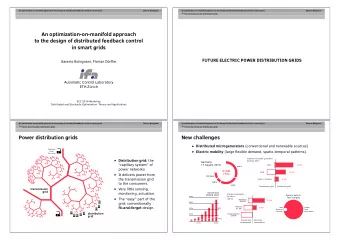
LLCB TBM & LLCS Objectives: Demonstrate T self-sufficiency (Li 2 TiO 3 and Pb-16Li breeders). High grade heat extraction (Helium and Pb-16Li coolants). LLCB Test Blanket Module [1] LLCS Process flow diagram [1] LLCB TBS System Design Description V1.0 26th IAEA Fusion Energy Conference - 2016, FIP/2-4 3
Motivation & challenges Pb-16Li a reference candidate material: requires validated measurement tools/technologies (for studies in lab-scale facilities, LM blankets). Operating parameters of LLCS & ITER operational cycle schedule: demand precise validation & reliable performance over long durations for effective blanket operation. LLCB TBS design identifies LLCS isolation safety functions based on: • Pb-16Li pressure measurement: TBM inlet/outlet (in-TBM LOCA). • Pb-16Li level measurement: Dump tank, sump tanks (in-vessel LOCA/ pipe rupture). Limited operational experience. Relatively high freezing point for liquid Pb & Pb-16Li. Limited instrumentation availability for LMs. Material compatibility. 26th IAEA Fusion Energy Conference - 2016, FIP/2-4 4
Sensor selection Application of Pb-Li: confined to fusion specific studies. Development of LM blanket concepts: triggered studies related to Pb-Li as a process fluid; requirement of technologies adapted to liquid Pb-Li. Steps followed for development of sensors: a) Proper selection of measurement technique • Commercial availability (diversification: reduces risk of common mode failure). • Performance history. b) Sizing of sensors • MOC (critical for wetted configuration). • Test environment considerations (temperature & pressure). • Installation constraints, process connections etc. c) Engineering modifications/customizations of COTS sensors • As applicable for specific requirements. d) Rigorous experimental validation for intended LM application • Application feasibility. • Calibration check. • Long duration performance validation (maintenance requirements / freq. of failures). 26th IAEA Fusion Energy Conference - 2016, FIP/2-4 5
(a) Pressure measurement Sensor Type: Piezo-resistive principle based remote diaphragm seal type pressure sensor Sensing element and electronics: mechanically isolated from HT process. Pressure transmission through high temperature compatible, incompressible, intermediate fluid (silicone oil / NaK) in a fine capillary ≤ 1mm bore diameter. Minimum volume displacement ensures better dynamic response. Wetted parts: SS-316/316L flush configuration diaphragm seal; Gasket: Grafoil. Operational principle of diaphragm seal Silicone oil filled capillary based NaK filled capillary based pressure sensor customized pressure sensor 26th IAEA Fusion Energy Conference - 2016, FIP/2-4 6
(b) Level measurement Sensor Type: Non-contact configuration pulse radar level sensor Immune to oxide/impurities deposition, corrosion, bending stresses. Distance measurement using TOF method (level estimation by configuration). Unaffected by process conditions (temperature, pressure, gas composition etc). Electronics is isolated from HT process using temperature isolator section. Operating frequency 26 GHz (K-band): smaller process connections, focused beam. Horn Antenna: SS-316L; Antenna cone: Ceramic (Al 2 O 3 ); Gasket: Grafoil. D = (C x Δ t)/2 L = H - D Operational principle of pulse radar level sensor Non-contact type pulse radar level sensor 26th IAEA Fusion Energy Conference - 2016, FIP/2-4 7
(c) TeLePro (Temperature Level Probe) Sensor Type: Customized K-Type multilevel thermocouple with thermowell Equidistant junctions (20 mm apart) provide bulk temperature profile. To study feasibility of development as a level sensing technique using differential bulk temperature measurement (abundance of data from multiple junctions for validation). Can be further enhanced for better accuracy, resolution and response. Limited by manufacturing feasibility and detectable temperature gradients. Schematic for TeLePro sensor assembly 26th IAEA Fusion Energy Conference - 2016, FIP/2-4 8
Test Facility-1: Design & constraints Schematic diagram of test facility-1 Level and pressure sensors installed on main tank Design constraints: Process Medium Liquid Pb • Maximum height of top nozzle • Minimum I.D. of main tank Operating Temp. 380°C – 400°C Liquid Pb as an economical substitute. Operating Upto 1 MPa (g) Pressure 10,584 kg/m 3 at Density of Pb 400°C M.P. of Pb 327.4°C Process parameters for test facility-1 Conductivity level switch construction and working principle 26th IAEA Fusion Energy Conference - 2016, FIP/2-4 9
Test Facility-1: Calibration & test methods For Pulse radar level sensor calibration: Known inventory of Pb ingots (405 kg). First calibration point: Using the total inventory of Pb, density of Pb at operating temperature & dimensions of test facility-1, liquid Pb level was analytically estimated & compared with radar level sensor output. Second calibration point: Liquid Pb was transferred to drain tank (upto 555 mm); remaining level in main tank was analytically estimated & compared with radar level sensor output. Over 700 hour continuous performance test with cover gas pressure upto 1 MPa (g) . For Silicone oil filled capillary based pressure sensor calibration: H effective = H – 145 mm where H is measured by validated radar level sensor P effective = H effective . ρ Pb . g P = P effective + P g Hence possible to vary total pressure applied to seal diaphragm by varying cover gas pressure (P g ) alone while ensuring that diaphragm seal is in contact with liquid Pb. Calculated total pressure P was compared with sensor output. Over 310 hour continuous test & cover gas pressure upto 1 MPa (g). Schematic for pressure sensor calibration 26th IAEA Fusion Energy Conference - 2016, FIP/2-4 10
Test Facility-1: Calibration & performance results Analytically Level indicated by Deviation estimated level radar level sensor (mm) (mm) (mm) 198.42 200.91 + 2.49 104.97 112.60 + 7.63 Calibration data for non-contact radar level sensor • Over 1000 hour test: [- 7.42 mm, + 9.58 mm] • Ambient Calibration check : [+ 1 mm, + 5 mm] Long duration test data for non-contact radar level sensor • Sources of error: Manually performed dimensional measurements, assumption of a constant bulk density, manual operation of isolation valve, error related to conductivity switch and accuracy of radar level sensor. • Data suggests absence of smooth melt surface: May be attributed to surface topography of oxide layers. • Validated for liquid Pb Validated for liquid Pb-16Li, other LMs and metallic alloys. Condition of diaphragm seal after exposure to liquid lead Estimated error over 310 hour test: Within 0.3% of span Long duration test data for diaphragm seal type pressure sensor 26th IAEA Fusion Energy Conference - 2016, FIP/2-4 11
Test Facility-2: Design Experimental validation of sensors: Process Medium Liquid Pb-16Li • Compatibility with HT, HP liq. Pb-16Li. • Operating Temp. 250°C – 530°C Deteriorating effects of corrosion. • Feasibility of level estimation using Operating Upto 1.05 MPa TeLePro concept. Pressure (g) Design optimized: 9318 kg/m 3 at Density of Pb-16Li Pb-16Li inventory ( ~ 23 kg). Tubing on side-section end 400°C Tubings between end of each side-section and top of tank-A M.P. of Pb-16Li 235°C (remove trapped gas volume & ensure proper drainage). Process parameters for test facility-2 Pressure sensors testing phase TeLePro assembly testing phase 26th IAEA Fusion Energy Conference - 2016, FIP/2-4 12
Test Facility-2: Calibration & test methods For Pressure sensors calibration: Effective Pb-16Li heads estimated using movable conductivity level switches. • For silicone oil fill fluid based pressure sensor : H1 effective = 66 mm • For NaK fill fluid based pressure sensor : H2 effective = 75 mm P effective = H effective . ρ Pb-16Li . g P = P effective + P g Two calibration cycles, each from 0 to 1 MPa (g) & vice-versa , at the start & end of continuous 1000 hour performance test. For TeLePro assembly testing: Continuous 1000 hour performance test. Afterwards, TeLePro development campaign: • Different cover gas pressures at a constant temperature CSP. • Different temperature CSPs at a constant cover gas pressure. • Heater control of tank-B using junction-1 of TeLePro. • Above temperature profiles were taken in steady state. Total test duration for TeLePro in liquid Pb-16Li ~ 1240 hours . Schematic for TeLePro testing as level sensor 26th IAEA Fusion Energy Conference - 2016, FIP/2-4 13
Recommend


More recommend
Explore More Topics
Stay informed with curated content and fresh updates.