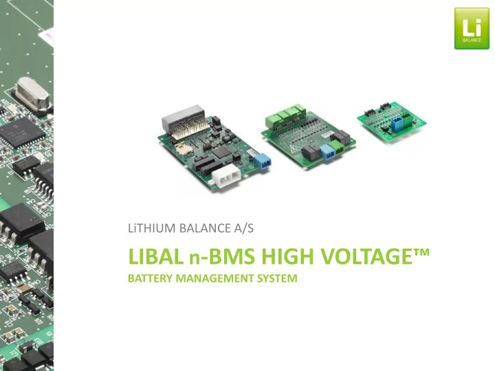

LiTHIUM BALANCE A/S LIBAL - BMS HIGH VOLTAGE™ n BATTERY MANAGEMENT SYSTEM
System overview BMS Creator™ 11 10 1. MCU 2.1 CMU 1 2.2 CMU 2 3. BATTRY PACK VCU 4. SHUNT/HAL 5. CHARGE CONTACTOR 6-34V 6. HV- MAIN CONTACTOR 9 7. HV+ MAIN CONTACTOR 2.2 8. PRE CHARGE CONTACTOR 8 1 9. CHARGER (CAN or PWM) 10. CAN DISPLAY 7 11. DIAGNOSTIC TOOL Resistor 2.1 HV + HV – 6 CELL MONITORING TEMPERATURE MONITORING 5 CAN 1 CAN 2 INPUT SIGNALS 80 80 80 80 80 80 80 80 3 OUTPUT SIGNALS % % % % % % % % 4 KEY SWITCH SoC SoC SoC SoC SoC SoC SoC SoC 4
System overview • 12 cells per Cell Monitoring Unit (CMU) • 32 CMU’s per system (384 cells in series) • Up to 12 or 4 temp sensors per CMU • All cell voltages measured in 150 [ms] • Current measured in 150 [ms] • Pack temperature measured in 150 [ms] MCU – Master Control Unit • 1,5 [mV] maximum cell voltage error • CMU error diagnostics on all inputs • MCU dual core master controller • MCU safe real time operating system CMU – Cell Monitoring Unit(s) • MCU safe power supply • MCU real time clock • 16 General Purpose I/O on MCU • 11 Temperature sensors on MCU CMU CMU CMU 100801 000705 100808
Safety • Robust key components • Realtime operating system (RTOS) at ASIL D level • All 4 safety critical functions has built in self-diagnostics meeting ASIL C level • Open wire detection • Build in leak detection
Performance • High speed main processor enables system to do advanced algorithms for high precision SOC. • BMS tested by leading Japanese automotive Tier 1, where SOC accuracy in a vehicle drive cycle show an impressive ±0,37% deviation (see below) • isoSPI internal communication protocol reduce the CMU cost and provide enable efficient service when software need to be updated in the field.
Lifetime optimization • Intelligent balancing and SOC algorithms enabled by high speed (150 ms) and accurate measurements (± 1,5mV). • Syncronized measurement of current, temperature and voltage ensure a precise status of each individual cell. MCU – Master Control Unit
n- BMS CREATOR™ • PC configuration tool with comprehensive CONNECT possibilities for customization • Enables the battery designer to create a UNIQUE BMS based on ”off the shelf” HW and SW platform • CONFIGURE Key Parameter configuration: – Error settings – Battery model – SOC model based on OCV – Current regulation CONTROL – I/O controls – CAN communication incl. full CAN open support – CAN Custom processing machine • Live view monitoring and Control • Service SERVICE
Specifications Module specifications Cells per CMU : 5 – 12 (min. 11 V) Cell voltage : 0,5 V – 4,5 V (0V – 5V with reduced accuracy) Cell voltage measurement accuracy : ±1,5mV (full temp. range) Cell voltage sampling frequency: 150 ms Temperature sensors: up to 12 or 4 per CMU Temperature measurement accuracy: ± 1⁰C Communication: isoSPI PCB Dimensions: MCU : 92mm x 166mm / CMU 92x118mm (new CMU 75x80mm) Balancing current: 200mA (at 4,2 V)
Specifications System specifications Supply Voltage: 6-34 (VDC) Pack voltage: Up to 1000 (VDC) Pack current : Up to 2000 (ADC) Communication : 1 isolated CAN bus (CAN 2.0A, CAN 2.0B up to 1Mb/s) and 1 non-isolated CAN bus Pack current measurement accuracy: ±0.2% maximum, with SHUNT sensor error: ±0.5% maximum (HOBUT CLASS 0.5 ) or HALL effect sensor error: ±1% maximum (LEM DHAB S/18) and @25°C Pack temperature and current sampling rate: 150 ms SOC, SOH calculations: Coulomb counting and OCV models Temperature range : Operational - 40⁰C to 85⁰C, Storage - 40⁰C to 105⁰C
Test and validation System tests CISPR 25: EMC susceptibility 150 kHz – 2 GHz ISO 11452: EMC susceptibility ISO 10605: ESD for road vehicles ISO 16750-2: Electrical Loads (Code A, Reversed, over voltage ect.) ISO 16750-3: Mechanical Loads (Sinusoidal and random vibration) ISO 16750-4: Climatic Loads ( Code G: -40 to 85°C) ISO 7637: Electrical disturbances from conduction and coupling
Recommend
More recommend