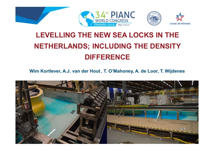

LEVELLING THE NEW SEA LOCKS IN THE NETHERLANDS; INCLUDING THE DENSITY DIFFERENCE Wim Kortlever, A.J. van der Hout , T. O’Mahoney, A. de Loor, T. Wijdenes
North Sea - IJmuiden Locks – Canal
North Sea Western Scheldt Estuary Terneuzen Locks Ghent-Terneuzen Canal
IJmuiden North Lock (1929), 400x50x15m 3 D h = - 0.3 m Û 1.6 m Mean spring tide Short culverts in lock heads gate openings
Terneuzen West Lock (1965), 355x40x13m 3 Canal = mean sea level + 2.1 m Mean spring tide D h = - 4.3 m Û 0.6 m Longitudinal filling system to reduce translatory waves and density currents
Design Approach Type of levelling system • Through-the-gate or short culverts • Longitudinal system IJmuiden daily D h = 1.4 m Terneuzen daily D h = 4 m through-the-gate/short culverts
Design Approach Dimensions • Through-the-head LOCKFILL: 1-D flow-force model incl. translatory waves, jets, density currents • Longitudinal system WANDA: 1-D model for nonstationary flow and pressures in closed conduits (without Dr ) Vertical position D h at start of opening gate Inlets/outlets at half the water depth Reduction of residual moment, horizontal force on gate, incoming translatory wave
Design Approach Hydraulic design Streamlining, shaping using 2-D/3-D CFD incl. turbulence Stationary flow Ø Flow conditions Ø Detachment points Ø Flow distribution Ø Loss coefficients Repeat 1-D LOCKFILL/WANDA using loss coefficients from CFD Nonstationary Density currents Different flow pattern during levelling Additional longitudinal/transverse forces on vessel Indicative CFD simulation with density currents
Lock exchange at North Lock
Design Approach Scale model 40 to 1 / 30 to 1
Design Approach Hydrodynamic force criterion
Reference Design New IJmuiden Lock Lock chamber: 545 m x 70 m x 17.25 m
Reference IJmuiden Ducts in gates or short culverts 14 ducts (14x2.2x3m 2 ) or 4 culverts (4x4x5m 2 ) at half the water depth Approach Chamber
Reference Design IJmuiden Scale model Ø Longitudinal and transverse forces exceed criterion due to density component Ø Valve speeds had to be reduced Ø Longer levelling times with gate ducts than with short culverts
New IJmuiden Lock Final Design
Final Design IJmuiden
Reference Design New Terneuzen Lock Lock chamber: 452 m x 55 m x 16.44m
Reference Design Terneuzen Ducts in gate Short culverts
Reference Design Terneuzen Longitudinal system with bottom grids Culverts 8 m x 4 m, total area at valves 60 m 2 Account for residual D h, residual forces on the gate Gates Bottom grid Culverts Chamber Gates
Reference Design Terneuzen Hydraulic design
Final Design Terneuzen Requirements Discharge capacity: m A = 34.5 m 2 Distribution between grids: 45%/55% Overtravel: 0.25 m Aiming at levelling time 15 min at D h = 4 m Contractor: ‘balancing the flow by bottom grids’
Conclusions • Include the density effect • New IJmuiden Lock D h = 1.4 m, T = 15-20 min, filling with salt water: ducts in gate • New Terneuzen Lock D h = 4 m, T = 15-20 min, filling with fresh water: longitudinal system • Residual head : link between levelling system design and gate design Terneuzen gates: extend initial phase, moving at creep speed
Thank you!
Recommend
More recommend