
Advanced Energy Systems, Inc. FY 09 AES Phase I Crab Cavity SBIR Progress Michael Cole (AES), Rama Calaga (BNL), Zenghai Li (SLAC)
Prototype Crab Cavity SBIR Objectives Advanced Energy Systems, Inc. • Collaborators are AES, BNL, SLAC, and LBL • Phase 1 – Preliminary Design of Cavity (3 man months supported by SBIR) • Coordinate transfer of Physics Design - Complete • Develop initial mechanical solid model - Complete • Perform Initial Thermal and Structural Analysis – Underway – Principle issue currently is cooling requirement for coaxial beam pipes • Preliminary Mechanical Design and Fabrication Feasibility Study – Largely Complete • Phase 2 – Complete mechanical design with supporting thermal/structural analysis. – Generate complete fabrication drawing package for the Crab Cavity. – Fabricate Prototype Crab Cavity – Perform BCP and HPR on Prototype Crab Cavity at AES if our facilities can accommodate it. We anticipate that we will be able accommodate an 800 MHz elliptical crab cavity. – Support Crab Cavity VTF testing at BNL
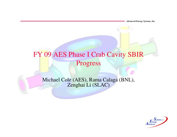
Overall Cavity Configuration Advanced Energy Systems, Inc. FPC END GROUP PORTS FOR LOM/HOM-v COUPLER ADJACENT BEAM PIPE, Accounted for but not included Double Walled Beam Pipe Inner Conductors FPC PORT Coaxial Beam Pipes SHORT END GROUP � Most of the cavity will be surrounded by a LHe vessel in the operational design but not in the prototype. � Cooling of the Beam Pipe Inner Conductors could be flood cooled 2K LHe or forced 5K He, this question is currently being addressed. � 5K He adds significant complications for VTA testing
Parted out Welded Assembly Advanced Energy Systems, Inc. � 39 Welding steps joining 32 parts will be required to fabricate each cavity. � In addition there are machining operations between many of the welds.
Welding Sequence A: Inner & Outer Conductor Advanced Energy Systems, Inc. 2 Welding steps required to connect the inner and outer 8 Welding steps conductor required to fabricate the inner conductor 6 Welding steps required to fabricate the outer conductor
Welding Sequence B: End Groups Advanced Energy Systems, Inc. 9 Welding steps required to fabricate FPC side End Group 2 Welding steps required to fabricate short side End Group
Welding Sequence C: Coax BP ICs Advanced Energy Systems, Inc. � 3 Welding steps are required to fabricate each double walled beam pipe inner conductor. � Fabricating the inner conductors in the fashion is actually cheaper than machining them from bar. They are too thick to roll and seam weld.
RF Analysis: Normalization Advanced Energy Systems, Inc. Magnetic Field (HY) Scaled for Transverse voltage of 5MV/cavity 4.0E+04 3.0E+04 Magnetic Field A/m 2.0E+04 1.0E+04 0.0E+00 -1.0E+04 -2.0E+04 -3.0E+04 -4.0E+04 0.0 0.2 0.4 0.6 0.8 1.0 Disatance Along Center of Cavity meters � Magnetic field on Axis used to normalize cavity fields. � Surface Fields will be used to calculate heat loads
RF Analysis: Surface H Fields and Initial Wall Powers Advanced Energy Systems, Inc. Surface Power Loss 2K = 11.2 watts 4.2K = 70.5 watts Magnetic Field A/m 2.14e-2 9.14e3 1.82e4 2.74e4 3.65e4 4.56e4 5.47e4 6.38e4 7.29e4 8.21e4
Work Remaining Advanced Energy Systems, Inc. • Phase 2 proposal due May 20 • Complete mechanical design work and determine fabrication cost for cavity • Complete thermal and structural analysis, primary concern will be cooling requirement for coaxial beam pipes • We are on track for May 20
Recommend
More recommend