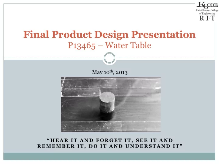

Final Product Design Presentation P13465 – Water Table May 10 th , 2013 “ H E A R I T A N D F O R G E T I T , S E E I T A N D R E M E M B E R I T , D O I T A N D U N D E R S T A N D I T ”
Water Table MSD Team 2 Primary Customers: Ed Hanzlik John Wellin Faculty Guide: Gerald Garavuso Team Members: John Harrington, Project Manager Andrew Nauss, Lead Engineer Timothy Jordan, Project Engineer Dan Abdeen, Project Engineer
Today’s Agenda 3 Introduction (3 minutes, 2 Slides) Brief Project Description Objectives / Customer Needs System Architecture (5 minutes, 4 Slides) Final System Design Capabilities System Demonstration (5 minutes, 1 Slide) Demonstration (Video) Testing (5 minutes, 4 Slides) Engineering Specifications / Test Plan Major Challenges Flow Separation Uniform Straight Flow Video Wrap-Up (10 minutes, 3 Slide) Budget Future Design Recommendations Questions and Comments
Project Description – Water Table 4 Force straight flow over an object of some geometry to study fluid dynamic effects Primarily used for displaying concepts of: ¡ Streamlines ¡ Flow Separation ¡ Vortex Shedding Top down view Variable flow speeds To be used for educational use Assist in fulfilling the ME department’s mission statement
Customer Needs 5
Final System Design (Side View) 6 Water Table Pump Switch Water E-Stop Reservoir Gate Valve 3-Way Valve Ball Valve
Final System Design (Top View) 7 Baffle/Inlet Test Section Nozzle Panel Drain Magnet Flow Straightener
Test Specimens 8 PLATE BERNOULLI CONTRACTION CYLINDER AIRFOIL
Main System Capabilities 9 Modular Transportable Quick setup and teardown No leaks Variable test specimen geometry Adjustable angle-of-attack Variable flow from 1 to 7.5 in/s Adjustable flow height from 1 inch to 5 inches Adjustable nozzle section Laminar flow regime only Two main flow visualizers: Ø Electrolysis Ø Beads Ø Food dye can also be used but limits duration of use w/o changing water Ability to measure velocity through high speed camera Possible future adaptability for fluids other than water and different setups Shows concepts of flow separation, vortex shedding, and streamlines
System Demonstration-Cylinder 10
System Demonstration-Airfoil 11
System Demonstration-Flat Plate 12
System Demonstration-Contraction Section 13
Engineering Specification / Test Plans 14
Major Challenges 15 Water Leak ¡ Problem: Water was leaking out of bulk head fitting due to uneven surfaces ¡ Solution: Used a Form-A-Gasket to create gasket for uneven surfaces Electrolysis ¡ Problem: Bubbles were created, but difficult to see ¡ Solution: Used underwater LED lights to emphasize bubbles by reflection of light
Flow Separation 16 According to theoretical results separation angle should occur approximately at 80 O from trailing end for 0.5 in/s flow velocity Separation angle using food dye was approximately at 80 O Separation angle using electrolysis was approximately at 80 O
Uniform Straight Flow Video 17 Uniform flow velocity throughout test section Distinct straight streamlines
Budget 18 Budget for project was $2000 Team spent ~$1800 Extra money was spent on buying additional replacement supplies such as platinum wire for future use
Future Design Recommendations 19 Modularity Design ¡ Completely redesigned to make setup easier Size of Water Table ¡ A longer and wider water table would allow for straighter flow and a larger test section capability Higher Voltage for Electrolysis ¡ More bubble generation ¡ Dangerous, but a cover could be made Deeper Water Design ¡ Deeper water design would allow the high mode on the pump to be used without it surging
Questions/Comments/Concerns 20 Thank nk ¡ ¡you ¡ ¡for ¡ ¡a,end nding ng ¡ ¡ our ¡ ¡Fina nal ¡ ¡Present ntation ¡ n ¡ Re Review! ¡ ¡
Velocity Flow Range Measurements 21 Measurements taken using a ruler and stop watch Velocity flow range: 0.8 in/s to 7.5 in/s
Recommend
More recommend