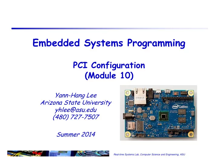

Embedded Systems Programming PCI Configuration (Module 10) Yann-Hang Lee Arizona State University yhlee@asu.edu (480) 727-7507 Summer 2014 Real-time Systems Lab, Computer Science and Engineering, ASU
PCI Address Space A PCI target can implement up to three different types of address spaces Configuration space Stores basic information about the device Allows the central resource or O/S to program a device with operational settings I/O space – Used mainly with PC peripherals and not much else Memory space – Used for just about everything else Message bus space message bus space is through the SoC’s PCI configuration registers 1 Real-time Systems Lab, Computer Science and Engineering, ASU
Accessing the Address Spaces accessed using a large variety of processor instructions (mov, add, or, shr, push, etc.) and virtual-to-physical address-translation accessed only by using the processor’s special ‘in’ and ‘out’ instructions memory (without any translation of port-addresses) space (4GB) PCI configuration space i/o space (16MB) (64KB) i/o-ports 0x0CF8-0x0CFF dedicated to accessing PCI Configuration Space 2 Real-time Systems Lab, Computer Science and Engineering, ASU
PCI Configuration Address Space Contains 256 bytes of basic device information, addressable by 8-bit PCI bus, 5-bit device, and 3-bit function numbers for the device the first 64 bytes (00h – 3Fh) make up the standard configuration header, including PCI ID , i.e. vendor ID and device ID registers, to identify the device the remaining 192 bytes (40h – FFh) represent user-definable configuration space, such as the information specific to a PC card for use by its accompanying software driver Also permits Plug-N-Play base address registers allow an agent to be mapped dynamically into memory or I/O space a programmable interrupt-line setting allows a software driver to program a PC card with an IRQ upon power-up 3 Real-time Systems Lab, Computer Science and Engineering, ASU
Memory and IO Spaces Memory space is used by most everything else – it’s the general -purpose address space The PCI spec recommends that a device use memory space, even if it is a peripheral An agent can request between 16 bytes and 2GB of memory space. The PCI spec recommends that an agent use at least 4kB of memory space, to reduce the width of the agent’s address decoder IO space is where basic PC peripherals (keyboard, serial port, etc.) are mapped The PCI spec allows an agent to request 4 bytes to 2GB of I/O space For x86 systems, #define IO_SPACE_LIMIT 0xffff because of legacy ISA issues 4 Real-time Systems Lab, Computer Science and Engineering, ASU
The Plug-and-Play Concept Allows add-in cards to be plugged into any slot without changing jumpers or switches Address mapping, IRQs, COM ports, etc., are assigned dynamically at system start-up For PNP to work, add-in cards must contain basic information for the BIOS and/or O/S, e.g.: Type of card and device Memory-space requirements Interrupt requirements 5 Real-time Systems Lab, Computer Science and Engineering, ASU
PCI Configuration Transactions Are generated by a host or PCI-to-PCI bridge Use a set of IDSEL signals as chip selects Dedicated address decoding Each agent is given a unique IDSEL signal Are typically single data phase Bursting is allowed, but is very rarely used Two types (specified via AD[1:0] in addr. phase) Type 0: Configures agents on same bus segment Type 1: Configures across PCI-to-PCI bridges 6 Real-time Systems Lab, Computer Science and Engineering, ASU
Type 00h Configuration Space Header 7 Real-time Systems Lab, Computer Science and Engineering, ASU
Configuration Commands Two DWORD I/O locations are used to generate configuration transactions 0CF8h references a read/write register, CONFIG_ADDRESS. 0CFCh references a read/write register, CONFIG_DATA. Bus enumeration attempting to read the Vendor- and Device ID register for each combination of bus number and device number, at the device's function #0 knows a device exists, and can then program the memory mapped and I/O port addresses for the device. 8 Real-time Systems Lab, Computer Science and Engineering, ASU
Example Quark GIP Configuratio lspci –s 00:15.2 –vvvxxx 00: 86 80 34 09 06 04 10 00 10 00 80 0c 00 00 80 00 10: 00 70 00 90 00 60 00 90 00 00 00 00 00 00 00 00 20: 00 00 00 00 00 00 00 00 00 00 00 00 86 80 34 09 30: 00 00 00 00 80 00 00 00 00 00 00 00 ff 03 00 00 40: 00 00 00 00 00 00 00 00 00 00 00 00 00 00 00 00 50: 00 00 00 00 00 00 00 00 00 00 00 00 00 00 00 00 60: 00 00 00 00 00 00 00 00 00 00 00 00 00 00 00 00 70: 00 00 00 00 00 00 00 00 00 00 00 00 00 00 00 00 80: 01 a0 03 48 08 00 00 00 00 00 00 00 00 00 00 00 90: 00 00 00 00 00 00 00 00 00 00 00 00 00 00 00 00 a0: 05 00 01 01 0c 10 e0 fe d1 41 00 00 00 00 00 00 b0: 00 00 00 00 00 00 00 00 00 00 00 00 00 00 00 00 c0: 01 00 00 00 00 00 00 c0 00 00 00 00 00 00 00 00 d0: 00 00 00 00 00 00 00 00 00 00 00 00 00 00 00 00 e0: 00 00 00 00 00 00 00 00 00 00 00 00 00 00 00 00 f0: 00 00 00 00 00 00 00 00 b1 0f 00 00 00 00 00 00 9 Real-time Systems Lab, Computer Science and Engineering, ASU
Recommend
More recommend