Distributed Systems - II If A is the event of sending a message by - PDF document
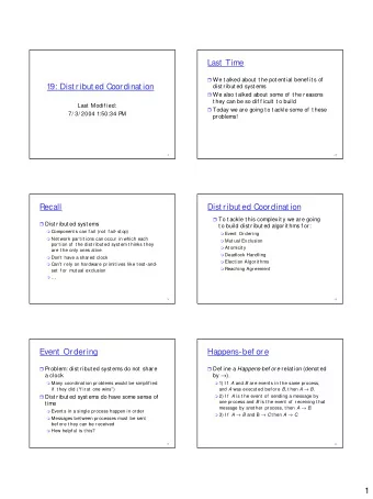
CSE 421/521 - Operating Systems Event Ordering Fall 2011 Happened-before relation (denoted by ) Lecture - XXIV If A and B are events in the same process (assuming sequential processes), and A was executed before B , then A B
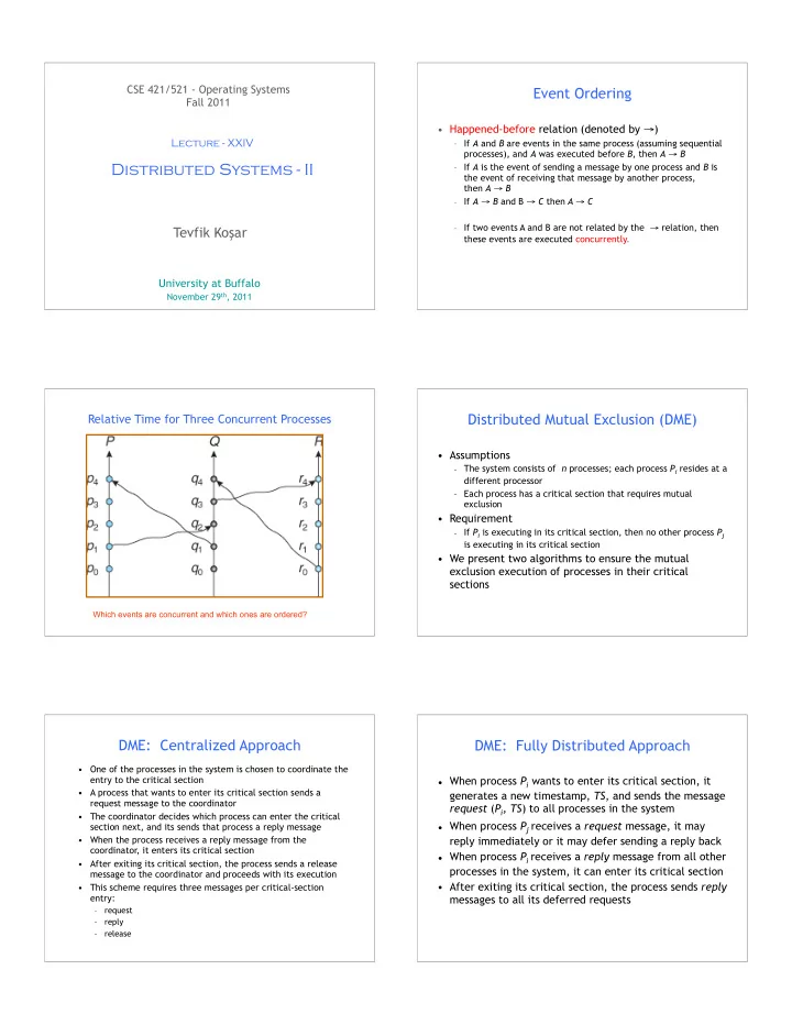
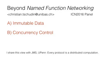
CSE 421/521 - Operating Systems Event Ordering Fall 2011 • Happened-before relation (denoted by → ) Lecture - XXIV – If A and B are events in the same process (assuming sequential processes), and A was executed before B , then A → B Distributed Systems - II – If A is the event of sending a message by one process and B is the event of receiving that message by another process, then A → B – If A → B and B → C then A → C – If two events A and B are not related by the → relation, then Tevfik Ko ş ar these events are executed concurrently. University at Buffalo November 29 th , 2011 1 Distributed Mutual Exclusion (DME) Relative Time for Three Concurrent Processes • Assumptions – The system consists of n processes; each process P i resides at a different processor – Each process has a critical section that requires mutual exclusion • Requirement – If P i is executing in its critical section, then no other process P j is executing in its critical section • We present two algorithms to ensure the mutual exclusion execution of processes in their critical sections Which events are concurrent and which ones are ordered? DME: Centralized Approach DME: Fully Distributed Approach • One of the processes in the system is chosen to coordinate the entry to the critical section • When process P i wants to enter its critical section, it • A process that wants to enter its critical section sends a generates a new timestamp, TS , and sends the message request message to the coordinator request ( P i , TS ) to all processes in the system • The coordinator decides which process can enter the critical • When process P j receives a request message, it may section next, and its sends that process a reply message • When the process receives a reply message from the reply immediately or it may defer sending a reply back coordinator, it enters its critical section • When process P i receives a reply message from all other • After exiting its critical section, the process sends a release processes in the system, it can enter its critical section message to the coordinator and proceeds with its execution • After exiting its critical section, the process sends reply • This scheme requires three messages per critical-section entry: messages to all its deferred requests – request – reply – release
DME: Fully Distributed Approach (Cont.) Token-Passing Approach • The decision whether process P j replies immediately to a • Circulate a token among processes in system request ( P i , TS ) message or defers its reply is based on three factors: – Token is special type of message If P j is in its critical section, then it defers its reply to P i – Possession of token entitles holder to enter critical section – • Processes logically organized in a ring structure – If P j does not want to enter its critical section, then it sends a reply immediately to P i • Unidirectional ring guarantees freedom from starvation – If P j wants to enter its critical section but has not yet entered it, then • Two types of failures it compares its own request timestamp with the timestamp TS – Lost token – election must be called • If its own request timestamp is greater than TS , then it – Failed processes – new logical ring established sends a reply immediately to P i ( P i asked first) • Otherwise, the reply is deferred – Example: P1 sends a request to P2 and P3 (timestamp=10) P3 sends a request to P1 and P2 (timestamp=4) Distributed Deadlock Handling Prevention: Wait-Die Scheme • non-preemptive approach • Resource-ordering deadlock-prevention • If P i requests a resource currently held by P j , P i is =>define a global ordering among the system resources – Assign a unique number to all system resources allowed to wait only if it has a smaller timestamp – A process may request a resource with unique number i only if than does P j ( P i is older than P j ) it is not holding a resource with a unique number grater than i – Otherwise, P i is rolled back (dies - releases resources) – Simple to implement; requires little overhead • Example: Suppose that processes P 1 , P 2 , and P 3 have • Timestamp-ordering deadlock-prevention timestamps 5, 10, and 15 respectively =>unique Timestamp assigned when each process is – if P 1 request a resource held by P 2 , then P 1 will wait created – If P 3 requests a resource held by P 2 , then P 3 will be rolled back 1. wait-die scheme -- non-reemptive 2. wound-wait scheme -- preemptive • The older the process gets, the more waits Prevention: Wound-Wait Scheme Comparison • Preemptive approach, counterpart to the wait-die system • Both avoid starvation, provided that when a process is rolled back, it is not assigned a new timestamp • If P i requests a resource currently held by P j , P i is allowed to wait only if it has a larger timestamp than • In wait-die, older process must wait for the younger does P j ( P i is younger than P j ). Otherwise P j is rolled one to release its resources. In wound-wait, an older back ( P j is wounded by P i ) process never waits for a younger process. • Example: Suppose that processes P 1 , P 2, and P 3 have • There are fewer roll-backs in wound-wait. timestamps 5, 10, and 15 respectively – Pi->Pj; Pi dies, requests the same resources; Pi dies again... – If P 1 requests a resource held by P 2 , then the resource will be preempted from P 2 and P 2 will be rolled back – Pj->Pi; Pi wounded. requests the same resources; Pi waits.. – If P 3 requests a resource held by P 2 , then P 3 will wait • The rolled-back process eventually gets the smallest timestamp. 12
Deadlock Detection Global Wait-For Graph Two Local Wait-For Graphs Local and Global Wait-For Graphs Deadlock Detection – Centralized Approach • Each site keeps a local wait-for graph – The nodes of the graph correspond to all the processes that are currently either holding or requesting any of the resources local to that site • A global wait-for graph is maintained in a single coordination process; this graph is the union of all local wait-for graphs • There are three different options (points in time) when the wait-for graph may be constructed: 1. Whenever a new edge is inserted or removed in one of the local wait-for graphs 2. Periodically, when a number of changes have occurred in a wait-for graph 3. Whenever the coordinator needs to invoke the cycle-detection algorithm • Option1: unnecessary rollbacks may occur as a result of false cycles Detection Algorithm Based on Option 3 Algorithm: Option 3 • Append unique identifiers (timestamps) to requests 1. The controller sends an initiating message to each site in the system form different sites 2. On receiving this message, a site sends its local wait-for graph to the coordinator • When process P i , at site A , requests a resource from 3. When the controller has received a reply from each site, it process P j , at site B , a request message with timestamp constructs a graph as follows: TS is sent (a) The constructed graph contains a vertex for every process in the system • The edge P i → P j with the label TS is inserted in the (b) The graph has an edge Pi → Pj if and only if local wait-for of A . The edge is inserted in the local - there is an edge Pi → Pj in one of the wait-for graphs, or wait-for graph of B only if B has received the request If the constructed graph contains a cycle ⇒ deadlock message and cannot immediately grant the requested resource *To avoid report of false deadlocks, requests from different sites appended with unique ids (timestamps)
Recommend


More recommend
Explore More Topics
Stay informed with curated content and fresh updates.