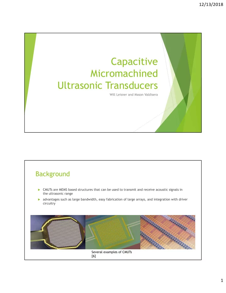

12/13/2018 Capacitive Micromachined Ultrasonic Transducers Will Leisner and Mason Valdisera Background CMUTs are MEMS based structures that can be used to transmit and receive acoustic signals in the ultrasonic range advantages such as large bandwidth, easy fabrication of large arrays, and integration with driver circuitry Several examples of CMUTs [6] 1
12/13/2018 History 1989: First 2006: First 1920s: Sonar Technology CMUT Flexible Developed developed CMUT 1950s: Ultrasound used 1994: First 2017: First in fetal imaging enclosed Transparent CMUT CMUT Theory – CMUTs combine principles of capacitors and beams Typical cross-section of a CMUT element [2] 2
12/13/2018 Theory – CMUTs can be used to transmit and receive ultrasound The principle behind how a CMUT works as an ultrasonic transducer [6] Theory – Testing and Characteristics Schematic of test set-up to determine Example of CMUT pressure and CMUT bandwidth and pressure [1]. bandwidth using the set-up described [1]. 3
12/13/2018 Fabrication – Sacrificial Layer (a) Substrate doping, etch-stop layer deposition, first sacrificial layer deposition and patterning. (b) Reduced etch channel height regions. (c) Active area definition. (d) Membrane deposition. (e) Sacrificial layer etch hole definition and Si3N4 etch. (f) Membrane release in KOH. (g) Membrane sealing with more Si3N4 deposition. (h) Top electrode deposition and patterning. An illustration of surface Sacrificial Release Process micromachining [8] [7] Fabrication – Wafer-bonding Preparation of wafers. (a) Through thermal oxidation, oxide layers are formed on the (b) surface of Wafer 1, then a spacer and 0.15 μm SiO2 insulating layer are formed using photolithography and wet etching. By low-temperature bonding, Wafer 1 and Wafer 2 are (c) bonded. The silicon substrate of Wafer 2 is eliminated. Subsequently, (d) the buried oxide layer of Wafer 2 is corroded away. The rest of Wafer 2 is processed by photolithography and (e) dry etching to form the isolation channel. In order to effectively isolate the top electrode and (f) vibration membrane, low pressure chemical vapor deposition (LPCVD) deposits SiO2. The top of Wafer 2 is sputtered with metal Aluminum. (g) In order to form the Aluminum electrode and metal bonding (h) pads, a lift-off process is used. Steps of the Wafer Bonding Method [2] 4
12/13/2018 Fabrication – Roll Lamination 2 Step Process First Step – Place Vibrating Membranes on PET release layer Second Step – Laminate Membranes onto Sidewall Membrane acts as CMUT Transparent, flexible CMUT Structural support walls manufactured using roll lamination [4]. 5
12/13/2018 Applications – Before Underwater Imaging, CMUTs were used in the Medical Field Cardiac Structures The vascular system The fetus and uterus Abdominal organs such as the liver, the kidneys, and gall bladder The eye Great at imaging moving systems Examples of Medical CMUT Images [5] Applications – Underwater Imaging Impacts a Wide Range of Markets Applications of Underwater Imaging [3] 6
12/13/2018 Applications – CMUT in Action • Tested in underwater tank • CMUT submerged in water along with target object • CMUT provides data to display the image shown in Testing of CMUT Device [1] figure b Conclusion – CMUTs are large contributors to Underwater Imaging Applications Provide imaging in low visibility water Better results than piezoelectric counterparts New manufacturing methods make CMUTs more efficient, cheaper, and accurate 7
12/13/2018 8
Recommend
More recommend