ARGONNES CLEAN ROOM TECHNIQUES FOR CRYOMODULE ASSEMBLY - - PowerPoint PPT Presentation

argonne s clean
SMART_READER_LITE
LIVE PREVIEW

ARGONNES CLEAN ROOM TECHNIQUES FOR CRYOMODULE ASSEMBLY - - PowerPoint PPT Presentation

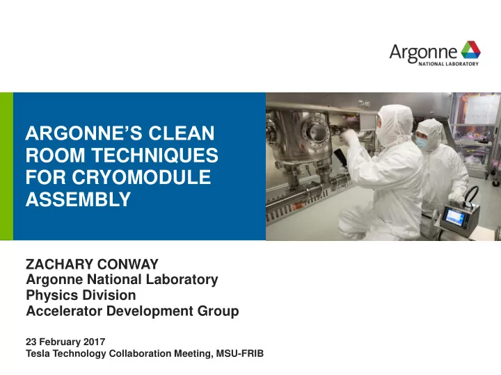
ARGONNES CLEAN ROOM TECHNIQUES FOR CRYOMODULE ASSEMBLY drhgfdjhngngfmhgmghmghjmghfmf ZACHARY CONWAY Argonne National Laboratory Physics Division Accelerator Development Group 23 February 2017 Tesla Technology Collaboration Meeting,


slide-1
SLIDE 1

ARGONNE’S CLEAN ROOM TECHNIQUES FOR CRYOMODULE ASSEMBLY

drhgfdjhngngfmhgmghmghjmghfmf

ZACHARY CONWAY Argonne National Laboratory Physics Division Accelerator Development Group

23 February 2017 Tesla Technology Collaboration Meeting, MSU-FRIB

slide-2
SLIDE 2

2

ARGONNE PERSONNEL WORKING ON THIS

  • Senior Physicists:

– M.P. Kelly (PHY), and – P.N. Ostroumov (PHY).

  • Physicists:

– Z. Conway (PHY), and – S.-h. Kim (PHY).

  • Engineers:

– M. Kedzie (PHY), – T. Reid (HEP), – B. Guilfoyle (HEP), and – W. Jansma (APS).

  • Designers:

– G. Cherry (NE).

slide-3
SLIDE 3

OVERVIEW

  • Subcomponent cleaning.
  • Cryomodule assembly.
  • Vacuum pumping and venting.
  • Installation in the beam line.
  • Brief summary.

3

72 MHz Quarter-Wave Resonator HPR

HPR Wand

Beam Line Cold Trap

slide-4
SLIDE 4

SUBCOMPONENT CLEANING - I

  • BCP/EP in the ANL/FNAL Joint

Superconducting Cavity Surface Processing Facility. – Processing cavities for ANL, – FNAL, – BNL, and more.

  • Hand tap all threaded holes.
  • Collect all the parts you will need

and have them ready.

4

ANL Low-b EP Tool With QWR HWR

slide-5
SLIDE 5

SUBCOMPONENT CLEANING - II

  • Wipe/scrub:

– Ethanol, – Acetone, – Dawn, – Alconox, and – Citrinox.

  • Ultrasonic clean:

– Alconox, 1-2% solution, or – Citronox, 1-2% soluition. – 1-2 hours. – Final DI H2O ultrasonic cleaning.

  • High pressure water rinse:

– All parts are high pressure water rinsed.

  • ANL’s low-b HPR tool used for the cavities and

solenoids.

  • Hand HPR of all parts and subcomponents.

– As much of the assembly is done during the HPR as is practicable. – Focus on cleaning and reducing future work.

5

HPR With Hand Held Nozzle QWR Beam Port HPR HPR of Strong-Back

slide-6
SLIDE 6

CLEAN ASSEMBLY

  • Assembly as many parts as possible during

the HPR. Things don’t get cleaner after this…

  • The cavities and solenoids are sealed in the

clean room after drying for ~48 hours and then transferred to the clean room where the beam line assembly is conducted.

  • Typically the first parts are cleaned weeks

before the final assembly.

6

  • All ports to be connected

during the final assembly are sealed with low- particulate covers/o-rings which can be removed smoothly.

  • Keep a distance from all
  • pen ports during the work.

– Operators do not make the clean room cleaner. – Special tooling may be required.

slide-7
SLIDE 7

VACUUM PUMPING/VENTING FLOW CONTROL SYSTEM

  • At Argonne the cryomodule pumping

and venting is controlled by a pair of mass flow controllers: – One for evacuating the volume. – One for venting the volume.

  • The flow rate is set to 50 mbar l/s.
  • The vent gas is filtered with a 0.003

mm diffuser.

  • The cryomodule pressure is held ~4

torr above atmosphere prior to

  • pening the clean assembly.
  • This system was used to replace all 7

pick-up probes on the 72 MHz QWR cryomodule operating in ATLAS since 2014 with no additional low- particulate cleaning.

7

  • K. Zapfe, SRF’07
  • S. Gerbick, SRF’09
slide-8
SLIDE 8

QWR PERFORMANCE AFTER 3 MONTHS ONLINE

8

10 W Replaced 1 beam-line gate valve and all 7 pick-up probes during cryomodule assembly.

slide-9
SLIDE 9

BEAM LINE INSTALLATION

  • Clean cryomodules are installed next to

non-clean accelerator hardware: – split-ring cavity cryomodules, – bunchers, and – experimental facilities/targets… etc.

  • To mitigate the risk of dirty beam lines

contaminating the clean cryomodules cold traps are installed on their inlet and outlet.

  • Liquid nitrogen cooled 8” or 12” long,

ϕ1.3” ID, copper tubes provide a cold surface for freezing out water, oil, etc.

  • All beam line connections are made in a

temporary clean room set-up over the beam line.

9

Cold Trap With and Without the Vacuum Vessel Shown

slide-10
SLIDE 10

SUMMARY

  • Using many techniques developed by members from the TESLA

collaboration.

  • All parts are cleaned and high pressure water rinsed.
  • After the HPR is finished we have a strong focus on reducing the

amount of work/handling required for the final low-particulate assembly.

  • Employ hardware to make sure the clean assembly stays clean:

– Vacuum pumping/venting system to control and filter the flow. – Beam line cold traps to help reduce contamination from adjacent, dirty, accelerator components.

  • Have employed these techniques on 2 cryomodules: 109 MHz QWR

and a 72 MHz QWR. Working on a 162 MHz HWR cryomodule now.

10