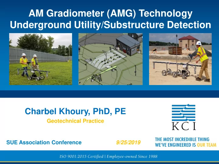

AM Gradiometer (AMG) Technology Underground Utility/Substructure Detection Charbel Khoury, PhD, PE Geotechnical Practice SUE Association Conference 9/25/2019
AM Gradiometer (AMG) Technology Table for Operation & Visualization
AMG Technology - Equipment Cart System
AMG Technology Equipment Portable System
AMG Technology Equipment Total Station Setup
AMG Technology - Transmitter
Typical Peak Signal/Detection
AMG Capabilities In general, AMG can detect the following subsurface items: • Electrical conductors (any type) • Metal pipes regardless of contents • Non-metallic conduits (fluid filled) • Liquid or Air-Filled Void-Space • Natural gas or fuel lines • Brick/concrete sewer lines • Shielded fiber optics cable • Hydrocarbon or Saline Moisture Plumes
AMG Capabilities/Limitations Typical depths-of-detection range up to 30 feet. Some large objects can be detected 30 to 50 feet with Antennas Adjustments AMG is NOT able to do the following: Identify the specific object detected Evaluate the diameter of the object detected Determine the contents of a pipe or conduit Differentiate between objects stacked in vertical Differentiate between two/multiple closely spaced Utilities; will “see” the bundle of pipes as a signal complex conductor. Provide accurate depth estimate for closely spaced utilities
Can detect anomalies Rarely detect non- regardless of their material conductive materials types (e.g., metallic, non- (i.e., plastics, ceramics) metallic, concrete) Cannot penetrate through Not limited by built-up materials like surface surface such as concrete, reinforced concrete, thin water, granite or moist/wet surfaces or when subsurface soil with high clay clay soils are encountered or moisture/water content Operates at higher Operates passively at a frequencies between 100 very low frequency (200 MHz to 2GHZ KHz to 1 MHz) Typical depths-of-detection up to 30 feet; however, can Typical depths-of-detection detect at 30-50 foot depths up to 10 feet with antenna configuration adjustments Typically does not Maps and provides detections with GPS coordinates/locations provide GPS locations and depths, which are easily and or depth data, but relies on 3 rd party surveying readily available for underground 3D models
Radio Stations AM Frequency - Transmittals Gospel Music 600KHZ News/Talk radio: 1090 KHZ
Example Projects • Regulator Stations • Sinkhole @ Howard St. & Pratt St. • Gas Gate Station • KCI North Ave. • Electric Substations (Sinkhole & Utilities)
Background Sept 2018 Columbia Gas Incident – Merimack Valley, MA System over-pressure damaged 131 structures One person was killed and at least 21 individuals taken to the hospital Aerial view of damaged home Structures damaged by the incident
Regulator Stations Control Lines Example of Typical Plan Drawing – Location 1
KCI Objectives/Approach Updated 2D drawing in “standard” Client’s format 3D BIM model of utilities and structures Augmented Reality (AR) KCI Practices Involved 1.Environmental (Project Management) 2.Geotech (AMG Technology, GPR coordination) 3. Utility Design (2D drawings in “standard” format) 4.Survey (Traditional survey & LaserScan) 5.SUE (Traditional mark out) 6.MEP (3D Modeling) 7.Geospatial (AR)
Pre-Field Work Activities
Field Work / Data Collection LiDAR & Traditional Survey SUE GPR AMG
Regulator Station - 1
AMG Data Collection Grid Pattern/ Transects – Location 1
2D Deliverable - Regulator Station 1
AMG - Regulator Station 1
GPR Deliverable GPR Results
Combining All of the Data – 3D Model
Test Pits – Regulator Station 1 1 2 2A 7 6 5 3 4A 4
Comparisons – Location 1 Variance (x,y) from surveyed utility as determined by Test Pits (feet) Location ID Description SUE AMG Client Plan 1 16” C.I. Main 1.0 1.0 N/A ¹ 2 8” Water Main N/A N/A 0.5 2A 16” C.I. Main 0.5 3.6 0.0 3 1” Control Line 1.5 0.7 0.2 4 1” Control Line 0.7 1.5 0.5 4A 1” Control Line 3.3 2.0 0.5 5 2 x 1” Control Lines 0.5 - 3.0 1.3 – 1.5 0.6 – 0.9 6 2 x 1” Control Lines 0.8 - 1.2 2.5 - 2.8 0.6 – 0.9 7 1” Control Line 2.25 0.8 0.3 ¹ Outside the area of AMG scanning
Location 1 – Variance Examples Location ID Description Client SUE AMG Final Drawing Plan 3 1” Control Line 1.5 0.7 0.2 Client Plan 4 1” Control Line 0.7 1.5 0.5 4A 1” Control Line 3.3 2.0 0.5 3 4 4 A AMG SUE 3 Final Drawing Final 3 4 4 Drawing A 4 4 4 A
KCI Approach – AMG Benefits Description SUE Mark Out Test Pits GPR AMG Identified known as well as No No Maybe Yes unknown utilities Not limited by site Yes Yes, but location No Yes conditions such as moisture, must be known clay, and concrete Not dependent on tracing No Yes, but location Yes, if not Yes wires or conductive must be known limited by site materials conditions Works on all types of No Yes, but location Maybe Yes utilities (cast iron, steel, must be known Non-metallic with or without tracer) Allows pinpointing of No No Yes, if not Yes utilities for vacuum limited by site excavation conditions
SINKHOLE @ Howard St. & Pratt. St. Sinkhole/Void W Camden St. Area S. Howard St. W Pratt St. Monday Afternoon July 8, 2019
SINKHOLE @ Howard St. & Pratt. St. Monday Evening July 8, 2019
SINKHOLE @ Howard St. & Pratt. St.
SINKHOLE @ Howard St. & Pratt. St.
SINKHOLE @ Howard St. & Pratt. St.
GPR Scanning GPR Survey Grid
GPR Scanning
GPR Scanning In the Roadway No underground or subsurface features were imaged below a depth of about 5 feet
AMG - Sinkhole Investigation Tuesday morning July 9, 2019
AMG Transects
AMG Findings Wednesday morning July 10, 2019
KCI SUE Plans
CSX Tunnel
AMG Technology
AMG Technology & Test Pit Test Pit
Test Pit Test Pit 22 ”
Success Points Rapid response to this emergency, and commitment of our Team Risk Mitigation : evidence that no significant void concerns are present along the Howard Street that may impact the roadway or the CSX Tunnel. KCI findings allowed on-going operation of emergency construction activities along the roadway
Augmented Reality 3-D Field Visualization
Recommend
More recommend