Active Stimulation of the Quasi Coherent Mode by External Antenna - PowerPoint PPT Presentation
Active Stimulation of the Quasi Coherent Mode by External Antenna T. Golfinopoulos, B. LaBombard, R.R. Parker, W. Burke, R. Granetz, M. Greenwald, R. Leccacorvi, R. Vieira, S. Wolfe, S. Wukitch et al. Quasi Coherent Mode (QCM) believed
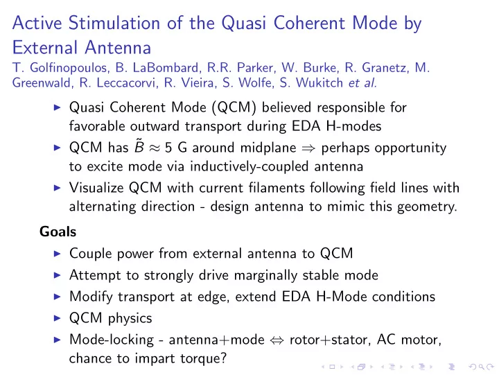
Active Stimulation of the Quasi Coherent Mode by External Antenna T. Golfinopoulos, B. LaBombard, R.R. Parker, W. Burke, R. Granetz, M. Greenwald, R. Leccacorvi, R. Vieira, S. Wolfe, S. Wukitch et al. ◮ Quasi Coherent Mode (QCM) believed responsible for favorable outward transport during EDA H-modes ◮ QCM has ˜ B ≈ 5 G around midplane ⇒ perhaps opportunity to excite mode via inductively-coupled antenna ◮ Visualize QCM with current filaments following field lines with alternating direction - design antenna to mimic this geometry. Goals ◮ Couple power from external antenna to QCM ◮ Attempt to strongly drive marginally stable mode ◮ Modify transport at edge, extend EDA H-Mode conditions ◮ QCM physics ◮ Mode-locking - antenna+mode ⇔ rotor+stator, AC motor, chance to impart torque?
Antenna Design ◮ La-doped Mo wire strung back and forth. ◮ Rapid radial decay ∝ e − k θ z ⇒ close to plasma ◮ Excited by variable-freq. source, 1 kW amp. or greater. ◮ Sweep frequency across (a) range of QCM; detect resonances, f response. ◮ Dwell at fixed f , mod. signal with slow square wave. (b) ◮ Bandwidth 50-300 kHz so Figure: (a) Antenna design Jan. ’11, Src.: R. WCM may also be targeted. Leccacorvi; Concept: B. LaBombard; (b) Wiring schem. for QCM sys. M ⇒ matching network, f -dependent
Run Time ◮ Piggyback 0.1 s or less at end of flattops, especially for EDA H-mode runs - allows us to assess antenna loading with plasma and calibrate matching network. ◮ Dedicated runs - start with Ohmic EDA H-mode plasmas described in Snipes2001 (QCM is well-characterized for these plasmas): 1. Low-field (3.2 T) to reduce H-mode threshold 2. Ramp up field (4.2 T) to achieve desired q 95 > 3 . 5 for QCM 3. Slowly reduce L-mode target density below n e = 1 . 3 × 10 20 m − 3 to make QCM marginally stable ¯ 4. Drive antenna, swept f and constant f with square-wave mod. ◮ Diagnostics: Fast Magnetics, PCI, GPI, Reflectometer, scanning probes (Langmuir+magnetic), HIREX Sr, Lyman- α
Recommend


More recommend
Explore More Topics
Stay informed with curated content and fresh updates.