
A A DVANCED W IRELESS W C SS T ECHNOLOGIES T ECHNOLOGIES Aditya - PowerPoint PPT Presentation
A A DVANCED W IRELESS W C SS T ECHNOLOGIES T ECHNOLOGIES Aditya K. Jagannatham Indian Institute of Technology Kanpur Indian Institute of Technology Kanpur Commonwealth of Learning Vancouver MOOC on M4D 2013 Wireless Signal Fast Fading
A A DVANCED W IRELESS W C SS T ECHNOLOGIES T ECHNOLOGIES Aditya K. Jagannatham Indian Institute of Technology Kanpur Indian Institute of Technology Kanpur Commonwealth of Learning Vancouver MOOC on M4D 2013
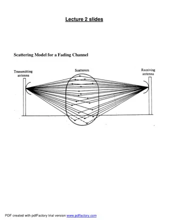
Wireless Signal Fast Fading Wireless Signal Fast Fading • The wireless signal can reach the receiver via direct and scattered paths. p • As a result, the receiver sees the superposition of multiple copies of the superposition of multiple copies of the transmitted signal. – Multipath Propogation • These signal copies experience different These signal copies experience different attenuations, delays. MOOC on M4D 2013 2
Wireless Signal Fast Fading Wireless Signal Fast Fading • Results in interference, amplifying or attenuating the signal power seen at the Rx. g g p – This phenomenon is termed as fading . • Strong destructive interference is referred to • Strong destructive interference is referred to as a deep fade. MOOC on M4D 2013
Techniques to Combat Fast Fading Techniques to Combat Fast Fading • Several techniques can be employed to Several techniques can be employed to improve performance in a wireless fading channel channel. – Forward Error Correction. – Interleaving. – Hybrid ARQ (HARQ). – Diversity. MOOC on M4D 2013 4
Forward Error Correction (FEC) Forward Error Correction (FEC) • System of error control for data transmission. S f l f d i i – Coding the data stream to correct at receiver. • Sender adds redundant data to its messages also known as ‘parity’ bits. p y • Examples of forward error correction codes, – Block Codes – Block Codes. – Convolutional Codes. – Turbo Codes. Turbo Codes • FEC typically uses a large overhead. MOOC on M4D 2013 5
Interleaving Interleaving • Symbol blocks to be transmitted. – Each symbol block is coded to protect against y p g symbol errors (Ex. Convolutional Coding). • Symbol blocks after Interleaving. – Interleaving arranges data in a non contiguous – Interleaving arranges data in a non ‐ contiguous fashion. MOOC on M4D 2013 6
Interleaving Interleaving • Deep fade results in a ‘Burst Error’ in the symbol p y block affected by fading channel. • Symbol blocks after Deinterleaving. Symbol blocks after Deinterleaving. – Erroneous symbols are spread across multiple blocks. • This results in better error correction performance for the block code. – It can correct a fixed number of errors per block. MOOC on M4D 2013 7
Hybrid Automatic Repeat reQuest Hybrid Automatic Repeat reQuest • It is an error ‐ control method for packet data transmission. • Uses ACKs/NACKs and timeouts to achieve reliable data transmission reliable data transmission. • An ACK is sent by the receiver to indicate that it has correctly received a data frame or packet. p MOOC on M4D 2013 8
Hybrid Automatic Repeat reQuest Hybrid Automatic Repeat reQuest • In case of a NACK, the receiver has two options in H ‐ ARQ. p – Send the complete packet (Chase Combining). – Send only the parity bits (Incremental – Send only the parity bits (Incremental Redundancy). • It cannot be used for transmission of real ‐ It t b d f t i i f l time information (Ex audio/ video). • Suited for non real ‐ time applications such as data e ‐ mail data, e mail. MOOC on M4D 2013
10
BER of a Rayleigh Fading Channel BER of a Rayleigh Fading Channel BER in a Fading Wireless Channel on Detectio r BPSK D BER in a wired BER for Channel SNR MOOC on M4D 2013 11
Antenna Diversity Antenna Diversity • Consider a wireless signal received using multiple antennas at the receiver (Rx) i.e. p ( ) employing receive antenna diversity. • Let the number of receive antennas be L • Let the number of receive antennas be L . • Hence, the receiver (Rx) sees L copies of the transmitted wireless signal, each traveling through an independent Rayleigh flat ‐ fading through an independent Rayleigh flat fading channel. MOOC on M4D 2013 12
Schematic of a Rx Diversity System Schematic of a Rx Diversity System Tx Tx Rx = Antenna MOOC on M4D 2013
Prerequisites for Diversity Gain Prerequisites for Diversity Gain • Diversity implies the receiver is provided y p p with multiple copies of the transmitted signal. • The multiple signal copies should experience independent levels of fading in the wireless p f f g channel. • This is because only in that case the • This is because only in that case the probability that all signal copies fade simultaneously is reduced dramatically simultaneously is reduced dramatically. – Leads to a significant reduction in the bit error rate. t MOOC on M4D 2013 14
BER of a Rayleigh Fading Channel BER of a Rayleigh Fading Channel BER in a Fading Wireless Channel on Detectio L = 1 r BPSK D L = 2 BER in a wired L 4 L = 4 BER for Channel L = 8 SNR With Rx Antenna Diversity MOOC on M4D 2013 15
16
Diversity Diversity • Examples of diversity techniques – Transmit/Receive Diversity. / y – Temporal Diversity. – Frequency Diversity. Frequency Diversity – Multipath Diversity. MOOC on M4D 2013 17
Spatial Diversity Spatial Diversity • As the name denotes, diversity can be obtained A th d t di it b bt i d by transmitting the wireless signal across independently fading spatial channels . independently fading spatial channels • This implies there are several receiving and/or transmitting antennas that are spaced transmitting antennas that are spaced sufficiently far apart. • Spatial separation should be sufficently large to Spatial separation should be sufficently large to reduce correlation between the different antennas or diversity branches. • Spacing guideline is approximately λ /2. At 2 GHz, the spacing is roughly 5 cm. MOOC on M4D 2013 18
Temporal Diversity Temporal Diversity • Temporal diversity is achieved through l di i i hi d h h transmission of same wireless signal at different times i.e. through temporal spacing. • The time separation between the signal p g copies should be larger than the coherence time of the channel for the different copies to p experience independent fading. • For instance at 2 GHz 60 Km/Hr the • For instance, at 2 GHz, 60 Km/Hr, the temporal spacing should at least be 2 ms. MOOC on M4D 2013 19
Frequency Diversity Frequency Diversity • Frequency diversity is achieved through F di i i hi d h h transmission of same wireless signal in different independently fading frequency bands i.e. i d d tl f di f b d i through frequency spacing . • The frequency separation should be larger than the coherence bandwidth B c of the channel. • For cellular communications this is approximately 300 KHz, since the delay spread is of the order of 3 μ s. MOOC on M4D 2013 20
Multipath Diversity Multipath Diversity • Signal replicas received are received at different Si l li i d i d diff delays and phase factors at the receiver. • If these different replicas are spaced sufficiently far apart so that they can be distinguished and they experience independent levels of fading, they can be used to exploit multipath diversity. • Receiver structures such as RAKE receiver in CDMA and equalizers such as Maximum q Likelihood Sequence Estimator (MLSE) in a TDM/TDMA system provide multipath diversity. y p p y MOOC on M4D 2013 21
MIMO Communication Systems MIMO Communication Systems • A MIMO system has multiple ( n t > 1) transmit y p ( t ) and multiple ( n r > 1) receive antennas. • MIMO wireless systems are a revolutionary MIMO wireless systems are a revolutionary breakthrough because they offer – Linear increase in throughput for the same Linear increase in throughput for the same transmit power – Combats fading through receive and transmit C b t f di th h i d t it diversity. MOOC on M4D 2013
MIMO System Schematic Diagram MIMO System Schematic Diagram T X R x R x X Receiver Receiver Transmitter Transmitter = Antenna MOOC on M4D 2013
MIMO Capacity vs SNR #Antennas MIMO Capacity vs. SNR, #Antennas MIMO Capacity vs. SNR (dB) for Different No. of Antennas 2 10 r = t = 1 r = t = 2 r = t = 4 r = t = 8 r = t = 8 /Hz) Capacity (b/s/ 1 10 C 0 10 5 10 15 20 25 30 35 40 45 50 SNR (dB) MOOC on M4D 2013
MIMO System Model MIMO System Model x y 1 1 y y x x MIMO 2 2 y x System y x n n r t • The MIMO system model can be represented as, k k k y ( ) Hx ( ) n ( ) . MOOC on M4D 2013
MIMO Capacity Schematic MIMO Capacity Schematic • The MIMO system can be schematically represented as having n t parallel channels. h ll l h l – Spatial Multiplexing Spatial nels Chann rallel S Pa MOOC on M4D 2013
S PACE ‐ TIME BLOCK CODES MOOC on M4D 2013
Recommend

More recommend
Explore More Topics
Stay informed with curated content and fresh updates.