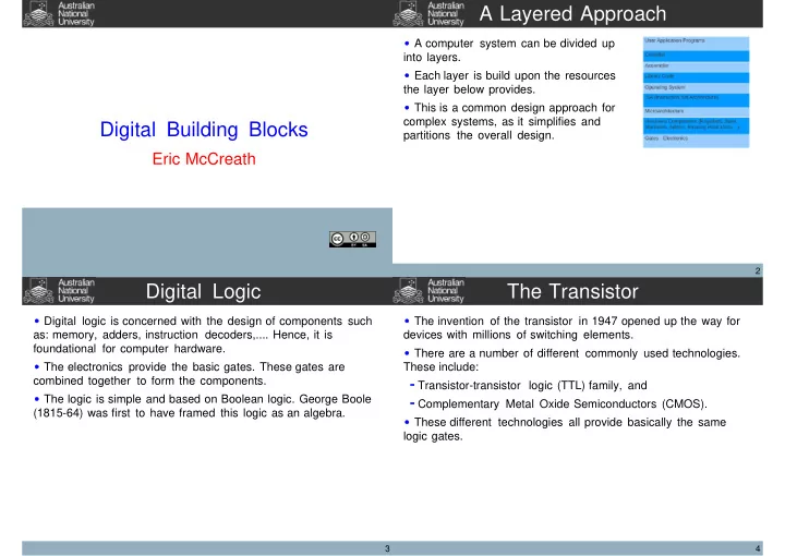

A Layered Approach A computer system can be divided up into layers. Each layer is build upon the resources the layer below provides. This is a common design approach for complex systems, as it simplifies and Digital Building Blocks partitions the overall design. Eric McCreath 2 Digital Logic The Transistor Digital logic is concerned with the design of components such The invention of the transistor in 1947 opened up the way for as: memory, adders, instruction decoders,.... Hence, it is devices with millions of switching elements. foundational for computer hardware. There are a number of different commonly used technologies. The electronics provide the basic gates. These gates are These include: combined together to form the components. Transistor-transistor logic (TTL) family, and The logic is simple and based on Boolean logic. George Boole Complementary Metal Oxide Semiconductors (CMOS). (1815-64) was first to have framed this logic as an algebra. These different technologies all provide basically the same logic gates. 3 4
The Transistor Switch not The transistor can act as a switch. The switch is a key The 'not' operator evaluates to true when the input is false, component in the construction of logic gates. otherwise it evaluates to false. 5 6 and or The "and" operator evaluates to true exactly when all its The 'or' operator evaluates to true when any of its inputs are inputs are true. true. (false otherwise) 7 8
xor nand The 'xor' operator evaluates to true when exactly one of its The 'nand' operator evaluates to true when any of its inputs inputs are true. are false. 9 10 nor Design to Truth Table The 'nor' operator evaluates to true exactly when all of its By using the truth tables of the basic gates we can always inputs are false. construct a truth table from a circuit design. 11 12
Truth Table to Design Instruction Decoder From any truth table we can also design set of gates that will Instructions are given a particular encoding. The architecture evaluate the truth table. must be able to determine if a particular instruction has been loaded. An instruction decoder can do this. Suppose the Note that, this design process goes beyond the scope of this instruction "add" has the encoding 0001 then the following course. circuit could decode it. 13 14 Binary Adder Binary Addition Binary addition is an important operation required by most We first create a component that will architectures. evaluate one column of the addition. When we add binary numbers by hand we place one number The inputs will be a single bit from each on top of the other. Then we move from right to left adding the binary number of the column in question. digits and remembering to include an carry. This exact approach Also the carry in will be provided to this can be replicated in digital logic. component. 00110 + 00101 -------- 01011 15 16
Binary Addition Full Adder We can construct a truth table for this one bit adder. From this truth table we can then design a circuit. Inductiveload, public domain, see: http://en.wikipedia.org/wiki/File:Full_Adder.svg 17 18 8 bit adder Exercises We can combine 8 of these 1-bit adders to form a serial 8-bit Work out the circuit for the below truth table: adder. Work out the truth table for the below circuit: A B Out C 19 20
Recommend
More recommend