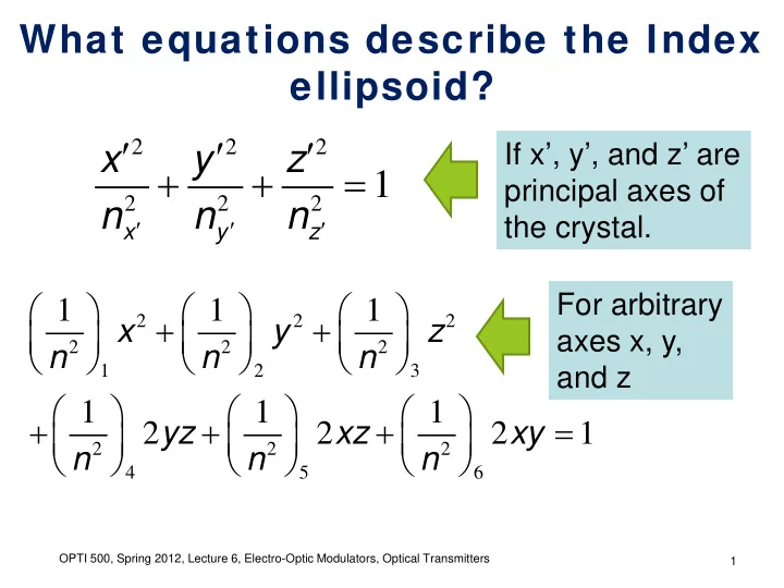

What equations describe the Index ellipsoid? ′ ′ ′ 2 2 2 If x’, y’, and z’ are x y z + + = 1 principal axes of 2 2 2 n n n ′ ′ ′ the crystal. x y z For arbitrary 1 1 1 + + 2 2 2 x y z axes x, y, 2 2 2 n n n 1 2 3 and z 1 1 1 + + + = yz xz xy 2 2 2 1 2 2 2 n n n 4 5 6 OPTI 500, Spring 2012, Lecture 6, Electro-Optic Modulators, Optical Transmitters 1
How do w e use the index ellipsoid? k (0,0,n z ) z θ (0,n y ,0) y (n x ,0,0) x • The waves that can propagate as linearly polarized waves have polarization along the major and minor axes of the ellipse perpendicular to the wavevector k . OPTI 500, Spring 2012, Lecture 6, Electo-Optic Modulators, Optical Transmitters 2
What is special about uni-axial crystals? k (0,0,n z ) z θ (0,n y ,0) y (n x ,0,0) x • n x = n y = n o • There is always a linearly polarized wave, called the ordinary wave, that “sees” a refractive index n o , regardless of the direction of propagation. OPTI 500, Spring 2012, Lecture 6, Electo-Optic Modulators, Optical Transmitters 3
What changes in the modulator to cause constructive interference to become destructive? z Optical Electrode Waveguide Optical y x Input Metal Electrode Modulated Optical Output Electrode Radiation Modes • The magnitude and/or direction of the applied electric fields. OPTI 500, Spring 2012, Lecture 6, Electo-Optic Modulators, Optical Transmitters 4
Are there any important corrections to the notes? 1 1 ( ) ( ) = − = − 2 3 n E n n r E n E n n r E 0 z 0 o 13 z o z o o 13 z 2 2 1 ( ) 1 ( ) = − 2 = − n E n n r E 3 n E n n r E e z e o 33 z 2 e z e e 33 z 2 • A large refractive index enhances the electro-optic effect. OPTI 500, Spring 2012, Lecture 6, Electo-Optic Modulators, Optical Transmitters 5
How did w e get the equations for LiNbO 3 ? 1 ∆ 2 n 1 1 ∆ − 2 n 0 r r 2 22 13 0 r r 1 1 1 ∆ ∆ = ∆ = 22 13 0 r E 13 z 2 2 2 n 0 0 r n n = ⋅ ⇒ 3 33 1 2 0 0 r 0 1 1 ∆ ∆ = 51 E r E 33 z z 2 2 r 0 0 n n 4 51 3 − 0 0 r 1 ∆ 22 2 n 5 1 ∆ 2 n 6 OPTI 500, Spring 2012, Lecture 6, Electo-Optic Modulators, Optical Transmitters 6
How did w e get the equations for LiNbO 3 ? 1 ∆ = r E 33 z 2 n 3 taking a derivative we find: 1 1 1 ∆ = ∆ = − ∆ 2 n e 2 2 3 n n n 3 e e 1 1 ( ) ⇒ ∆ = − = − 3 3 n n r E and n E n n r E e e 33 z e z e e 33 z 2 2 OPTI 500, Spring 2012, Lecture 6, Electo-Optic Modulators, Optical Transmitters 7
How does LiNbO 3 compare w ith other electro-optic materials? From “Optoelectronics” by Pollock OPTI 500, Spring 2012, Lecture 6, Electo-Optic Modulators, Optical Transmitters 8
Can w e have a quadratic electro- optic effect? ( ) = + + 2 n E n a E a E 0 1 2 Linear Kerr Refractive − Effect Electro Index optic Effect ( Pockels Effect ) OPTI 500, Spring 2012, Lecture 6, Electo-Optic Modulators, Optical Transmitters 9
Recommend
More recommend