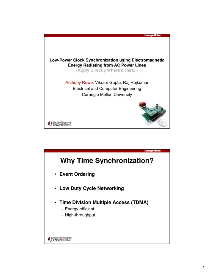

Low-Power Clock Synchronization using Electromagnetic Energy Radiating from AC Power Lines Energy Radiating from AC Power Lines (Apply Directly Where it Hertz ) Anthony Rowe, Vikram Gupta, Raj Rajkumar Electrical and Computer Engineering Carnegie Mellon University Why Time Synchronization? • Event Ordering • Low Duty Cycle Networking • Time Division Multiple Access (TDMA) – Energy-efficient – High-throughput 1
Looking back at 2006 Mobile Drill Gateway Hole Hazardous Infrastructure Mobile Node Obstruction Node 3 NIOSH Research Coal Mine near Pittsburgh Leaky Feeder Transmitter T itt 4 NIOSH: National Institute for Occupational Safety and Health 2
Very Complex. Expensive. Power Grid Antenna AM Transmitter Carrier Current Adapter Nodes 5 Other Synchronization Approaches • Sensor Network Time Synchronization – Flooding Time Sync Protocol, FireFly-inspired Time Sync Reference Broadcast Sync, Reference Broadcast – What about energy? – Imagine extremely low duty-cycles… • Global Broadcasts – WWVB atomic clock, GPS, Radio Data Service (RDS) – Does not work well indoors • Simultaneous Observations – Quasar Pulses, Quantum Entangled Particles – Not practical (yet) 3
Wirelessly Receive Power-Line Magnetic Field Mains Powerline “Syntonization” vs Synchronization • The 60 Hz frequency from the electrical line acts as a common global clock source l b l l k • The phases will differ depending on the angle of the receiver with respect to the magnetic field • Signal due to imbalances in grounding loops Mains Powerline 4
Powerline 60 Hz • Field Strength – Home • 17 milli gauss (as much as 10 gauss) • 17 milli-gauss (as much as 10 gauss) – Industrial • As much as 100 gauss – Power Line • 3 milli-gauss at 60 meters – Earth • .02 milli-gauss • Stability Stability – 10 -5 stability (typical oscillator is 10 -5 ) – 10 -8 differential delay stability between two points – Many old alarm clocks and appliances used the sine wave from direct contact to lines as a cheap clock Clock Sources Eastern Eastern Western Western Interconnect Interconnect Texas Interconnect 5
Why use a Syntonistor ? • Once phase offsets have been established, the device remains synchronized for long the device remains synchronized for long periods of time without exchanging messages • Errors can be detected by monitoring for rapid changes in the 60Hz signal Challenges Inductance / • Low-power receiver Resonance • Robustness to noise PLL Filtering • Common time reference WSN Protocol • Absolute phase adjustment 6
Block Diagram Variable Gain Gain Raw Signal Zero Amplifier Software PLL Crossing (jitter) Phase Offset Pulse Per Second Error Cycle Counting Counting Micro-Controller Sensor Node Syntonistor Syntonistor Hardware PIC12F683 Tank Circuit Tuned to 60Hz 7
Syntonistor Hardware PIC12F683 1 st Amplifier / High-Pass Filter Syntonistor Hardware PIC12F683 2 nd Amplifier / Auto-Gain 8
Syntonistor Hardware PIC12F683 Zero-Crossing Detector Syntonistor Hardware PIC12F683 Micro-controller 9
Tank Circuit (low Q)? High Q, Low L Good amplification Low Q, High L Large Raw Signal The raw signal O-scope with delay 10 second persistence 10
Phase-Locked Loop (PLL) • Adjust period of output signal based on phase difference compared to input signal phase difference compared to input signal • Classic controls problem • We used a Proportional-Integral-Derivative We used a Proportional Integral Derivative (PID) controller – Low gains with reasonable I-term since we do not require extremely fast convergence Cleaning up the jitter 11
Protocol (1 of 2) 1 1. Build Spanning Tree Build Spanning Tree 2. Flooding Time Synchronization - Determine phase offset from initial epoch 3. Phase Offset Adjustment Protocol (2 of 2) • Simple • MAC protocol independent 12
Synchronization Energy (1 of 2) • Ideal non-adjusted approach – Send a packet when local clock drift exceeds required synchronization i d h i ti • Assume perfect re-sync and ideal MAC protocol • LPL-CSMA (B-mac) rate adjusted – Add a MAC protocol to Ideal approach, but now we apply clock rate adjustment based on multiple packets • Syntonistor – Consumes 58 μ W Synchronization Energy (2 of 2) 13
Experimental Setup Opto- Syntonistor isolator 100 ft Opto- Syntonistor isolator LOGIC PC ANALYZER Opto- Syntonistor isolator Step-Down Transformer To AC Line FireFly running Nano-RK • C GNU tool-chain • Classical Preemptive Operating System Multitasking Abstractions • Real-Time Priority-Based Scheduling CC2420 – Rate-Monotonic Scheduling ATmega1281 • Built-in Fault Handling • Resource Reservations – CPU, Network, Transducer Resource Control – Forms Virtual Energy Budget http://www.nano-rk.org 14
8 nodes, 10000 ft 2 , 11 days Interference • Indoors – High Frequency sources are bad (computers, TVs, etc.) – Some devices are good (lights, etc.) S d i d (li ht t ) – Transformers radiate a clean signal for multiple meters • AC adapters are like transmitters • Outdoors – Strong signal 50 meters from buildings – Near power lines (buried or above ground) works very well – Surprising where one finds power lines 15
Limitations • No Mobility – Due to low frequency – Due to low frequency • Only operates near power – Not good for the ocean, space or remote areas • Requires extra hardware (cost) R i t h d ( t) – This can be optimized Conclusion • Developed a hardware device that locks onto the magnetic field from power lines – Consumes 58 μ W Consumes 58 μ W – Ambient magnetic filed energy is already there • Using a high-level protocol, network-wide synchronization is possible – Typically less than 1 ms accuracy • Remains synchronized without exchanging any packets • Locally detects errors without sending packets 16
Thank You. Questions? 17
Recommend
More recommend