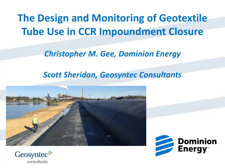

The Design and Monitoring of Geotextile Tube Use in CCR Impoundment Closure Christopher M. Gee, Dominion Energy Scott Sheridan, Geosyntec Consultants CONFIDENTIAL
Chesterfield Power Station Lower Ash Pond 2 2
Layout of the Lower Ash Pond (LAP) Ash Management Operations Area 1 Operational Pool 3
Why the Use of Geotubes was Selected? Dominion wanted to start the Intermediate Water Management Plan (IWMP) for the Lower Ash Pond (LAP) while continuing the operate the pond – Initially, Dominion desired to implement the IWMP by December 2018 – Chesterfield Power Station needed to continue sluicing CCRs to the Lower Ash Pond through December 2017 while the station was being converted from wet to dry ash handling • Design Consideration - One of the VPDES limit for the operating pond was TSS • The IWMP needed to control sediment runoff from the filling of Area 1 Initial Approach – Use of Sheet Piles Walls – Sheet piles required a platform for access, 50 ft – Concern with embedment depths including possible impacts to underlying natural soils. How could the IWMP target date be met? Geotubes Design Considerations for Using the Geotubes – Safety during installation – Environmental compliance must be maintained during installation – Stability during and after installation 4 4
Layout of the Lower Ash Pond (LAP) Ash Management Operations Area 1 Operational Pool 5
Field Investigations SPT (2015) CPT (2015) FFP (2016) 6
Geotechnical Investigation Full flow CPT cone tip CPT sleeve Field SPT N- penetrometer ball pressure (tsf) friction (tsf) values (bpf) tip pressure (psf) 0 0 0 0 100 40 20,000 4 Coal Combustion Residuals Alluvium Stronger Cretaceous Sediments 7
Sheet Pile Wall Concept 30 8
Geotextile Tube Wall Concept Construct a geotextile tube wall between Area 1 and pool side Fill geotextile tubes with ash dredged from the operational pool Geotextile tubes will act as a gravity structure to improve stability while fill is placed on land side Geotextile tubes provide BMP for maintaining compliance with discharge permit during filling and grading in Area 1. 9
Polymer Laboratory Testing Bench-scale testing with multiple polymers and multiple dosages Goal: identify polymer that will most improve the dewatering process 10
Slope Stability Analysis 11
Stability of Construction of Geotextile Tube Wall Pad 12
Stability of Construction of Geotextile Tube Wall Cumulative Critical Calculated Met Geotextile Tube Target Cross Construction Condition FS Target Filling Height FS Section (min. 1.3) FS? (ft) C First geotextile tube layer, first filling 2 1.30 1.3 Yes C First geotextile tube layer, second filling 5.5 1.32 1.3 Yes C Second geotextile tube layer, first filling 8.5 1.30 1.3 Yes C Second geotextile tube layer, second filling 11 1.31 1.3 Yes Placement of final cover with 5 ft B 11 1.36 1.3 Yes of stockpile Placement of final cover with 5 ft of B 11 1.74 1.5 Yes stockpile – long-term conditions 13
Construction of Geotextile Tube Wall Lesson Learned • Provide additional positive slope, anticipating settlement and construction impacts, for liner to reduce ponding at tubes while filling. 14
Construction of Geotextile Tube Wall Lesson Learned • Provide additional grading behind the geotubes for stormwater control under varying conditions, keeping in mind the tubes act as a dam. 15
Construction of Geotextile Tube Wall Lessons Learned • Polymer dosing can be highly variable during the dredging operations, so a thorough monitoring plan that provides the ability to adjust dosing is necessary. 16
Pore Pressure Monitoring Design Engineer Input Lessons Learned • Provide adequate space for Design Engineer Input piezometer readouts so they are not too close to the geotubes for future monitoring • Strong communication of monitoring program and expectations. 17
Aerial View of Post Construction Condition of Geotextile Tube Wall Construction Geotextile Tube 1 Geotextile Tube 2 18 18
Post Construction Gradation of Ash in Tubes 19 19
Post Construction %Moisture of Ash in Tubes 20 20
Lessons Learned / Effectiveness A thorough monitoring plan is needed to track the dosing rate. Stormwater controls should be considered under varying conditions. On this project, pore pressures dissipated quicker than expected. The geotubes provided effective separation between construction and operations. The structural fill was placed successfully within Area 1 without any compliance or stability issues. The condition of the ash in the geotubes may or may not vary, depending on the variable of dosing, runoff control, filling sequence, and time. Geotubes were more cost-effective than sheet pile wall installation. 21 21
Recommend
More recommend