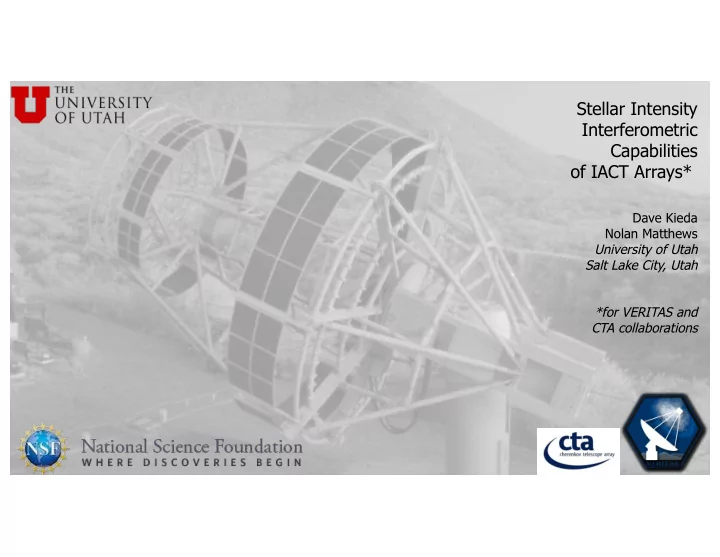

Stellar Intensity Interferometric Capabilities of IACT Arrays* Dave Kieda Nolan Matthews University of Utah Salt Lake City, Utah *for VERITAS and CTA collaborations
Photon Bunching & Intensity Interferometry D= Correlation Distance
3 SII Imaging → Basic Intensity Interferometry 𝜇 B 𝐽 " Measures correlation in R intensity fluctuations (not amplitude!). R. Hanbury Brown, J. Davis and L. R. Allen , MNRAS 137 (1967) 375.
4 SII Imaging → Basic Intensity Interferometry 4 Some Pains, But Large Gains: 𝜇 -Relatively insensitive to atmospheric turbulence ( turbulence ~ kHz, sampling ~100’s MHz ). B - Km Baselines possible, operate at blue wavelengths ->sub milli-arcsecond resolution 𝐽 " -No need to maintain steady optical interference path between focal planes. -> higher order intensity correlations possible Measures correlation in intensity fluctuations -Loss of phase information: (not amplitude!). → Phase recovery needed.
� � 5 Signal to Noise Ratio (SNR) in Intensity Interferometry Hanbury Brown 1974; Twiss 1969 Light collection area How to Improve? q.e. of detectors Example Calculation: -Multi-Channel Photo-electron Rate -10 9 p.e./sec (m v = 1.0, A=100 m 2 Intensity Interferometer: = 0.3 ) 𝑂 %& improvement, -10 13 Hz (for 10nm filter) Optical Bandwidth (Trippe, 2015) Electronic Bandwidth -250 MHz -Redundant baselines: 𝑂 ()* improvement. -1 hour observation Integration Time - dual polarization -Fast optics & correlators Normalized Visibility -Assume unresolved = 1.0 (> 1GHz). Spectral Flux Density SNR = 200 (assuming ideal system, limited to bright sources) (ph s -1 m -2 Hz -1 )
� � 2 nd -order time coherence g (2) & Fourier Image plane g (1) (u, v, t) : first-order coherence =1 for [u, v, t=0] g (2) (0,0,0) g (4) u, v, 0 = E I l, m e I"JK *LMNO d𝑚 𝑒𝑛 I l, m describes the image size and brightness distribution (Van Cittert-Zernike Theorem 1934,1938) Lab measurement of g (2) (0, 0, t ) of simulated star/thermal light Matthews, Kieda & LeBohec , accepted in J Opt (2017) 𝐽 𝑚, 𝑛 +, - /+, . / = g (2) (u, v, t ) = 1 + ½ g (1) (u, v, t) ½ 2 +, - , . / 𝑛 For II: experimental time resolution ∆𝑢 ~ 1 nsec blackbody coherence time 𝑢 % ~ 4 ∆5 ⁄ ~ 10 psec g (2) (0,0,0) = 1 + 𝜗 ~ 1 + 10 -4 small non-Gaussian fluctuations 𝑚 => Need large photon counts: 10+ m mirrors Reconstructed SII laboratory images stellar disk (left) & binary system (right) Matthews, Kieda & LeBohec , accepted in J Opt (2017)
Potential SII at Optical Telescope Arrays VERITAS IACT Array VLTI- Paranal Future CTA/pSCT Array 100 m 1-2 km Excellent instruments for SII: • • -Large photon collection area (~10 m diameter mirrors) • -Optically isochronous (< 5 ns) 100 m to km baselines (milli-arcsec resolution) J. Holder and S. LeBohec, Ap. J . 649 (2006) 399 D. Dravins et al., New Astronomy Reviews 56 , 5 (2012) 143
Potential VERITAS SII Augmentation VERITAS Camera 499 PMT pixels Dual polarization SII pixel (replaces 3 Center PMTs)
GPS Timecode Generator SII Data Quality Monitor 1 PPS 10 MHz 10 GB Ethernet WR-SWITCH Module Telescope 2 Single Mode Fiber 50m - 2 km (80 km max) Telescope 3 plastic plastic fiber fiber Telescope 4 Telescope N Telescope 1 120 ft double shielded RG 223
Standalone telescope connected Typical SII GPS Timecode Generator SII Data Quality Monitor only by fiber optic (White Rabbit, 10G) 1 PPS 10 MHz Augmentation 10 GB Ethernet WR-SWITCH Module Telescope 2 Single Mode Fiber 50m - 2 km (80 km max) Telescope 3 plastic plastic fiber fiber Telescope 4 Telescope N Replace with Custom board in camera? Telescope 1 120 ft double shielded RG 223
Simple VERITAS interferometer simulation Simulated baselines 100 𝜈 𝑏𝑠𝑑𝑡𝑓𝑑 Fourier image Plane sampling (vertical) *`ghost images’ caused by incomplete sampling of Fourier plane *reflection symmetry of ghost images caused by loss of phase information S. Lebohec et al. 2009
http://www.cta-observatory.org/ 1-2 km baselines 20-100 telescopes
Simulated Fourier image Planes Reconstructed Binary images Input Binary images Simulated observations of binary stars with different sizes. (m V = 3; T eff = 7000 K; T = 10 h; D t = 1 ns; l = 500 nm; Dl = 1 nm; QE = 70%) Already changes in stellar radii by only a few micro-arcseconds are well resolved. Better sampling of Fourier image plane-> no ghost images D.Dravins, S.LeBohec, H.Jensen, P.D.Nuñez:, CTA Consortium Optical intensity interferometry with the Cherenkov Telescope Array, Astropart. Phys. 43, 331 (2013)
f = 5.6m, D = 9.6m,FOV= 8° Pixel= 6mm ( × 11,328SiPMs) PSF D68 = ~0.04 –0.08° (pix= 0.06°) CTA-US Schwarzschild-Couder Telescope Prototype is Currently under construction at VERITAS Observatory (Fall 2017 commission)
Schwarzschild-Couder two-mirror IACT telescope Wide field of view, excellent spot size RMS spread in arrival time of rays at focal plane as a function of field angle. . On-axis: photon timespread <0.2 nsec rms >>improved g (2) ( t ) >>reduced observation time 2-4Ghz sampling + SiPM (QE-0.9). SNR = 200 -> SNR =2400 ! V. Vassiliev, S. Fegan, P. Brousseau: Wide field aplanatic two-mirror telescopes for ground-based g -ray astronomy Astropart.Phys . 28, 10 (2007)
IACT Observatories are Excellent Instruments for SII Imaging • Digitizing electronics/White Rabbit synchronization Standalone telescopes connected by inexpensive fiber optics. • • 1-10 km baseline separations now achievable • Offline (post-observation) photon correlations Polarization data allows higher S/N, baseline noise estimation • Demonstrated correlation using of pipelined FPGA for near real-time processing • • Higher order correlations may contain additional image information (Ofir & Ribak 2006) • Near Term Implementation • VERITAS Telescopes (Potential deployment/use in 2017-2018) • 100-200m baselines: 100 𝜈 arcsec imaging possible • Longer Term Development • VLTI visible light feed /single board implementation? • CTA/SCT-telescope array implementation : 1-2 km baselines, <100 𝜈 arcsec imaging?
Recommend
More recommend