
SOFTWARE ARCHITECTURE For MOLECTRONICS John H. Reif Computer Science Dept Duke Univ. In Collaboration with: Allara, Hill, Reed, Seminario, Tour, Weiss DARPA Moletronics Program
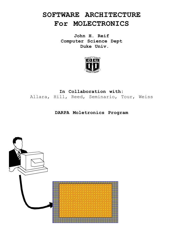
BLACK BOX ARCHITECTURE: Moletronics Processing Array Contains basic logic gates Surrounded by: Reconfigurable Interconnects INPUTs: X = vector of m data inputs Y = vector of l control inputs X Y OUTPUT: O(X,Y) O(X,Y)= vector of n outputs Initial Conditions of System: Ø random interconnects Ø meaningless output for a given data input
KEY MOLECTRONICS SOFTWARE DESIGN CONSTRAINTS: ♦ Moderate Number (say 1000) of Inputs ♦ Large Number 2 1000 of Possible Single-bit Output Values 100 of Possible I/Os ♦ Very Large Number >10 ♦ Extremely Large Number 2 1000000 Possible Functions which can be I/O Combinations ♦ Very Large Percent of Defective Fabricated Components Ø Key Technical Challenge: Need high fault tolerance MOLECTRONICS PROGRAMMING FLEXIBILITY: ♦ Rewire interconnect topology using strong fields: Ø Re-program undesired & inoperative outputs ♦ New Interconnect Routes Between Nanoparticles Ø Use electrochemically induced crosslinking e.g., add pyrrole to form new wire interconnects ♦ Increasing Memory Capability: Ø Attach During Assembly: Ø Add More DRAM Elements: Semiconductor Nanoparticle/controllers ♦ Choosing Functional Elements: Ø Use Òburning outÓ approach Ø Hard-wire specific Elements into Final System
GENERAL MOLECTRONICS SOFTWARE DESIGN CONCEPT: SELF-RECONFIGURABILITY via TRAINING (e.g., UCLA/HP Teramac) [1] TRAIN MOLECTRONICS System to compute function F(X) To Obtain Correct Output F(X) for data input X (e.g., a basic logic function) Repeatedly: Vary Control Inputs Y until Stability F(X) = O(X,Y) is achieved at Control Input vector Y 0 [2] VERIFY Training: verify F(X) =O(X,Y 0 ) in absence of changes in Y 0 ♦ MODULAR Functional Training: Ø determine & separate key functional modules to be executed Ø separately train & test modules ♦ ADVANTAGES: to give the correct F(X) Ø No detailed system reconfiguration Ø Need not know exact interconnect structure Methods that may Speed Up Convergence: Ø Evolutionary Programming Techniques Ø Simulated Annealing Techniques Ø Nested Annealing Techniques [Reif]
DYNAMIC ERROR RESILIENCY ♦ Key Software Problem: PROGRAMMING a moletronic computer to do useful computations when: Ø Use highly UNRELIABLE components Ø Some components may be only PARTIALLY functional ♦ Coping With Dynamic Faults: Programming Needs To Do: Ø Efficient DETECTION of Faulty Components on an ongoing basis Ø REPAIR Faults by Bypassing Faulty Components ERROR-RESILIENT PROGRAMMING TECHNIQUES: (1) Fault Resiliency Using REDUNDANCY [von Neumann 1950s] (2) MODULAR Fault Resilient Software Architecture e.g., [Gacs,1989][Gacs,Reif,1990] (3) Task RE-ASSIGNMENT e.g., [Kar, Nikolaou,Reif,1984]
ERROR-RESILIENT PROGRAMMING TECHNIQUE #1 Fault Resiliency Using REDUNDANCY [von Neumann, 1950s] Ø Transform Digital Circuit with Faulty Components Using 3-way Redundancy Ø Replicate Logical Components and use Majority Voting Replication Majority Voting
ERROR-RESILIENT PROGRAMMING TECHNIQUE #2: MODULAR Fault Resilient Software Architecture [Gacs,1989][Gacs,Reif,1990] Ø Use Hierarchical Structured Fault Detection and Correction Ø Decision Making via Majority o-Director Co-Director Co-Director Level 2 Level 2 Level 2 Manager Manager Manager Level 1 Level 1 Level 1 Manager Manager Manager processor processor processor
ERROR-RESILIENT PROGRAMMING TECHNIQUE #3: Task RE-ASSIGNMENT [Kar, Nikolaou,Reif,1984] Ø Re-Mapping Algorithm Uses Decomposition of Task Network Ø Re-Mapping to Sub-Network of Reliable Components
Additional Slides on TESTING METHODOLOGY for MOLECTRONICS
TESTING METHODOLOGY for MOLECTRONICS: ♦ Testing System: may be Symmetric MultiProcessors (SMPs) ♦ Interface to Testing System: Ø During Assembly: via I/O leads Ø After Assembly: via input & output wires ♦ Multiple Testing Stages in Fabrication & Assembly ♦ Components to be Tested: Individually & In Place
TESTING for DIGITAL RESPONSE: DETERMINING FAULT LOCATIONS ♦ COMPONENT I/O Tests: For each logical component: Ø Test if usable truth table output obtained Ø Cycle through subsets of inputs to determine truth tables ♦ BUNDLED I/O Tests: Ø Decreases Number of I/O testing Combinations Ø Increases Likelihood of Overcoming Single Fault Locations ♦ AGGREGATE Fault Testing on Subcircuits: Ø May employ Sophisticated Software Routines developed for VLSI testing [Reif, 1993]
MEASURING and MODELING ANALOG RESPONSE ♦ 1 st Year: using 2D probed configuration may use hybrid on-chip multiplexer INITIAL VALIDATIONS: characterize & tune: Ø electrode configuration, Ø individual components, Ø signal value/thresholds [1] APPROXIMATE Numerical Parameters Ø signal thresholds Ø response curves [2] Develop Software MODELS: Ø for component performance [3] TUNE MANUFACTURE of Components Ø Goal : INCREASE YIELDS of working Components [4] Use ITERATIVE REFINEMENT of Above ♦ In Later Years: Ø Full 3D structure NOT always Accessible to Surface Probes Ø Will Use Previously Developed Numerical Software Models
Recommend
More recommend