Pin Power Reconstruction with Leakage-corrected Embedded Calculation - PDF document
Transactions of the Korean Nuclear Society Virtual Spring Meeting July 9-10, 2020 Pin Power Reconstruction with Leakage-corrected Embedded Calculation in PWRs Hwanyeal Yu*, Seongdong Jang*, and Yonghee Kim* *Korea Advanced Institute of Science
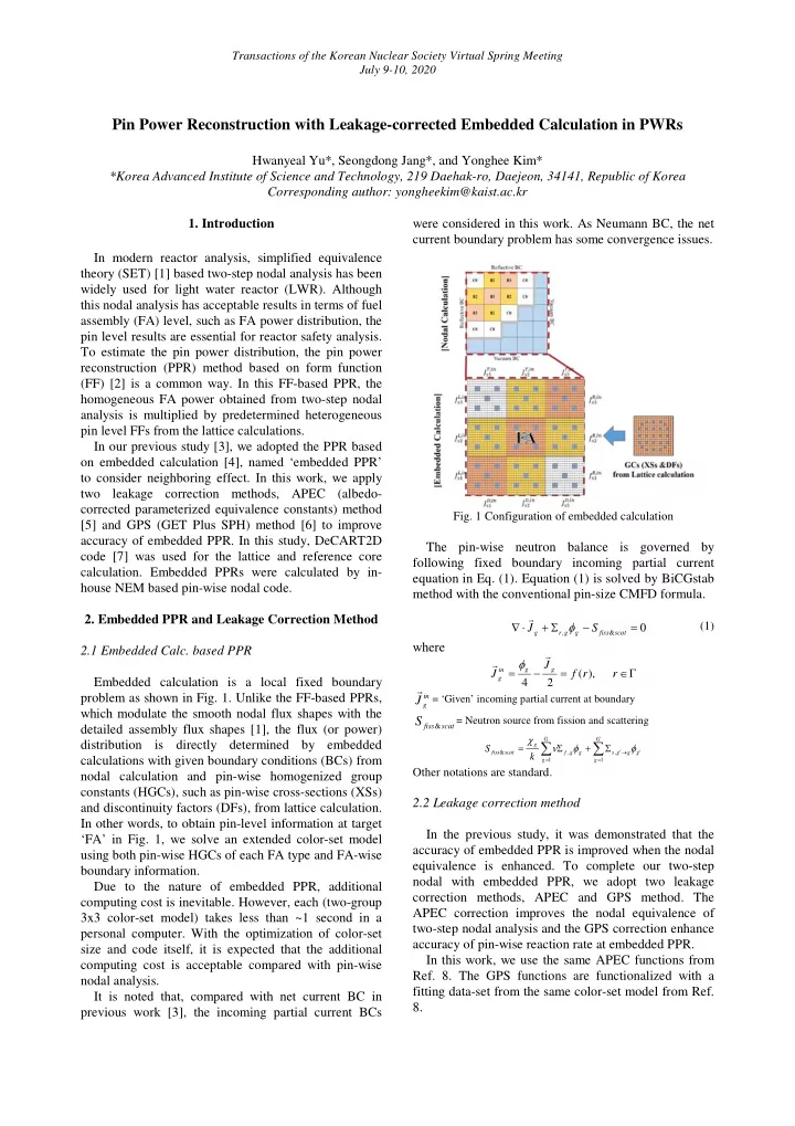
Transactions of the Korean Nuclear Society Virtual Spring Meeting July 9-10, 2020 Pin Power Reconstruction with Leakage-corrected Embedded Calculation in PWRs Hwanyeal Yu*, Seongdong Jang*, and Yonghee Kim* *Korea Advanced Institute of Science and Technology, 219 Daehak-ro, Daejeon, 34141, Republic of Korea Corresponding author: yongheekim@kaist.ac.kr 1. Introduction were considered in this work. As Neumann BC, the net current boundary problem has some convergence issues. In modern reactor analysis, simplified equivalence theory (SET) [1] based two-step nodal analysis has been widely used for light water reactor (LWR). Although this nodal analysis has acceptable results in terms of fuel assembly (FA) level, such as FA power distribution, the pin level results are essential for reactor safety analysis. To estimate the pin power distribution, the pin power reconstruction (PPR) method based on form function (FF) [2] is a common way. In this FF-based PPR, the homogeneous FA power obtained from two-step nodal analysis is multiplied by predetermined heterogeneous pin level FFs from the lattice calculations. In our previous study [3], we adopted the PPR based on embedded calculation [4], named ‘embedded PPR’ to consider neighboring effect. In this work, we apply two leakage correction methods, APEC (albedo- corrected parameterized equivalence constants) method Fig. 1 Configuration of embedded calculation [5] and GPS (GET Plus SPH) method [6] to improve accuracy of embedded PPR. In this study, DeCART2D The pin-wise neutron balance is governed by code [7] was used for the lattice and reference core following fixed boundary incoming partial current calculation. Embedded PPRs were calculated by in- equation in Eq. (1). Equation (1) is solved by BiCGstab house NEM based pin-wise nodal code. method with the conventional pin-size CMFD formula. 2. Embedded PPR and Leakage Correction Method ∇ ⋅ + Σ φ − = (1) J S 0 g r , g g fiss & scat where 2.1 Embedded Calc. based PPR φ J = − = ∈ Γ g g in J f ( r ), r g Embedded calculation is a local fixed boundary 4 2 problem as shown in Fig. 1. Unlike the FF-based PPRs, in = ‘Given’ incoming partial current at boundary J g which modulate the smooth nodal flux shapes with the S = Neutron source from fission and scattering detailed assembly flux shapes [1], the flux (or power) fiss & scat χ G G ∑ ∑ distribution is directly determined by embedded = ν Σ φ + Σ φ g S ′ → ′ fiss & scat f , g g s , g g g k calculations with given boundary conditions (BCs) from = = g 1 g 1 Other notations are standard. nodal calculation and pin-wise homogenized group constants (HGCs), such as pin-wise cross-sections (XSs) 2.2 Leakage correction method and discontinuity factors (DFs), from lattice calculation. In other words, to obtain pin-level information at target In the previous study, it was demonstrated that the ‘FA’ in Fig. 1, we solve an extended color-set model accuracy of embedded PPR is improved when the nodal using both pin-wise HGCs of each FA type and FA-wise equivalence is enhanced. To complete our two-step boundary information. nodal with embedded PPR, we adopt two leakage Due to the nature of embedded PPR, additional correction methods, APEC and GPS method. The computing cost is inevitable. However, each (two-group APEC correction improves the nodal equivalence of 3x3 color-set model) takes less than ~1 second in a two-step nodal analysis and the GPS correction enhance personal computer. With the optimization of color-set accuracy of pin-wise reaction rate at embedded PPR. size and code itself, it is expected that the additional In this work, we use the same APEC functions from computing cost is acceptable compared with pin-wise Ref. 8. The GPS functions are functionalized with a nodal analysis. fitting data-set from the same color-set model from Ref. It is noted that, compared with net current BC in 8. previous work [3], the incoming partial current BCs
Transactions of the Korean Nuclear Society Virtual Spring Meeting July 9-10, 2020 3. Numerical Results Table. 1 Numerical results of two-step nodal analysis ∆ ρ FA pow %error Condition keff Max. (RMS) [pcm] 3.1 SMR benchmark core UOX-loaded SMR Ref. DeCART2D 1.07492 To test the performance of embedded PPR with Two-step Nodal 1.07657 142.40 1.58 (1.04) leakage correction method, two small PWRs were APEC-corrected Nodal 1.07481 -10.03 0.79 (0.52) selected as shown in Fig. 2. One of them is partially Partially MOX-loaded SMR MOX-loaded SMR which is the most difficult Ref. DeCART2D 1.05380 Two-step Nodal 1.05774 352.89 2.52 (1.13) benchmark problem in LWR. APEC-corrected Nodal 1.05389 7.43 0.82 (0.44) a) UOX-loaded SMR 1) Configuration of FAs b) Partially MOX-loaded SMR Fig. 3 Reference FA power and %error of nodal analysis (octant core) 3.2 Numerical results of PPR Two conventional PPRs, FF-based and embedded PPRs, were performed based on results of nodal analyses. Figure 4 shows maximum and RMS %error between reference pin-power and reconstructed pin- power distribution of FF-based PPR. Figure 5 2) Core layout of UOX-loaded SMR shows %error for embedded PPR. It is noted that the embedded PPR provides more accurate pin-power distribution compared with the FF-based PPR since the embedded PPR can take into account the neighborhood effects by extended problem domain. a) UOX-loaded SMR 3) Core layout of partial MOX-loaded SMR Fig. 2 Core configuration of two SMR cores Table 1 shows numerical results of nodal analyses. Figure 3 shows the reference normalized FA power and corresponding FA power % error of nodal analyses. The results of two-step nodal are quite typical and APEC b) Partially MOX-loaded SMR correction improved the nodal equivalence as expected. Fig. 4 Reconstructed pin power %error of FF-based PPR
Transactions of the Korean Nuclear Society Virtual Spring Meeting July 9-10, 2020 PPR is slightly higher than that of FF-based PPR, it has acceptable accuracy. Furthermore, embedded PPR has less maximum and RMS pin-power %error at corresponding FA. As mentioned above, the FF-based PPR solution also has the same limitation that caused by FF. In addition, a) UOX-loaded SMR the homogeneous flux distribution of FF-based PPR is determined by FA-wise information, which also has the inevitable error. In these regards, the embedded PPR solution has better accuracy. 3.3 Embedded PPR with APEC correction b) Partially MOX-loaded SMR To investigate the improvement of embedded PPR by Fig. 5 Reconstructed pin-power %error of embedded PPR leakage correction method, APEC correction is firstly Figure 6 shows the reconstructed pin-power %error analyzed. Figure 7 shows FA-wise maximum and RMS distribution of partially MOX-loaded SMR. Similar to reconstructed pin-power %error of embedded PPR of APEC-corrected nodal calculation. According to our the inevitable error of pin-wise HGCs in conventional two-step nodal analysis [6], both FF-based and previous study [3], FA-wise RMS %error of embedded embedded PPRs have the same limitation. It causes PPR has a similar trend with FA power %error of two- relatively large pin-power %error at the interface step nodal analysis. In this regard, it is expected that the accuracy could be improved if the nodal equivalence is between different FAs and peripheral pins near baffle- enhanced. Figure 7 demonstrates it, especially in terms reflector regions as shown in Fig. 6. of RMS %error. As shown in Fig. 8, however, similar level of maximum %error is occurred at peripheral pins of FA. This means that it is caused by error of pin-wise HGCs. It is expected that the accuracy of embedded PPR could be improved in terms of FA-wise maximum pin-power error as long as GPS function corrects the pin-wise reaction rate a) FF-based PPR a) UOX-loaded SMR b) Partially MOX-loaded SMR b) Embedded PPR Fig. 7 Reconstructed pin power %error with APEC correction Fig. 6 Reconstructed pin-power %error distribution of partially MOX-loaded SMR (octant core) In the case of the embedded PPR of partially MOX- loaded SMR, the maximum pin-power error, 6.00%, occurs at the corner pin which faces two MOX FAs, where normalized pin-power is 0.711. At the same location, however, FF-based PPR has a higher pin- power error, 8.11%. The maximum normalized pin-power is around 1.542, and corresponding pin has about -0.63% (FF-based PPR) and -1.09% (embedded PPR) pin-power error. Fig. 8 Reconstructed pin-power %error distribution of Although corresponding pin-power error of embedded partially MOX-loaded SMR with APEC correction
Recommend


More recommend
Explore More Topics
Stay informed with curated content and fresh updates.