
Phase II Shaun Alsum 1
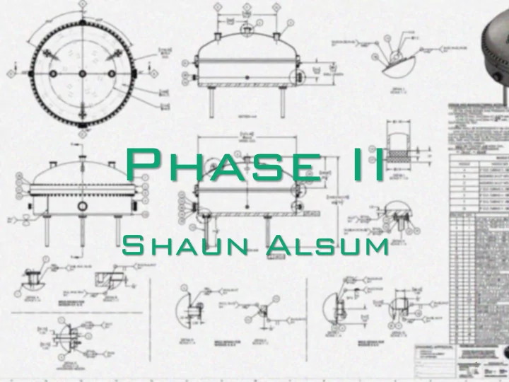
What Is Phase II? • 500+ kg LXe detector • 2m diameter outer vessel, 1.6m inner • Looks like Hamburger = 2
What is it for? • Testing full-sized LZ grids (1.5m diameter!) – Preproduction grids: study grid responses – Final LZ grids: quality control • Look for – sparking – electron emission Examples of imperfections in wires that may distinguish two 3 otherwise identical grids
Proposed Test Plan 5 Grid sets • Preproduction 1: bottom parameters, 1/3 scale • Preproduction 2: bottom parameters, full scale (~1.5m) • Bottom: .75mm wire diameter, 5mm pitch • Cathode: (1cm, 5mm) • Gate + Anode: full extraction region (.75, 5), (1, 2.5) Grid Liquid Extraction Preproduction 1 Conditional No Preproduction 2 Time permitting Conditional Bottom Yes No Cathode Yes Conditional Gate + Anode Yes (over gate) Yes 4
Proposed Test Plan: Preproduction Time + Gas Fill infrastructure Base Plan permitting Ramp Repeat Liquid Fill No Sparks or problems excess e - Voltage Consistent Scratch Quick tests Ramp Heads, but then Voltage Sparks or excess e - Repeat Recover 5
Proposed Test Plan: LZ Grids Gas Fill Hold Surface Fields 2 Repeat Liquid Fill No Sparks or problems excess e - Hours Consistent Scratch Quick tests Hold Surface Heads, but then Fields 3 Days Sparks or excess e - Repeat Recover 6
The Vessels Inner Vessel Outer Vessel 7
Vessel features • 3 top ports • 4 evenly spaced side ports, 2 big (4” diameter inner), 2 small (2” diameter). Same-size adjacent • 3 feet, evenly spaced at a radius of 27.5” 8
How’s it going to work? • Wide pressure vessel • Minimal internal structure – Not meant to mock up LZ, just the grid surface fields (excepting extraction region during gate- annode test only) – Grid: supported by stands, or small tpc-like sections – PMTs: probably suspended independent of any TPC-like structure – Wier: likely just a tube or tubes 9
P&ID In Progress… 10
Grid section For gate-anode, full extraction region will be mounted Field Shield Liquid level Grid Grid support rod, stub, or TPC section 11 Spacer/thermal plate with liquid distribution channels
Weir Section - Simpler 12
Weir Section – More Complex Instrumentation Cabling 13
Weir Section – More Bells and whistles Sightglasses 14
Cooling - Bottom Not pictured: copper straps from bottom up sides (and maybe around to LN lines for top) initial cooldown Copper Thermal Plate One Coldhead for LN lines run the whole bottom 15 along the bottom
Cooling - Top One coldhead for the entire top: dubious Straps or LN may also be desired for the top. 16
Grid Storage Main TS + LN Vessel HEPA Filters HV FT Cab- North Lid Storage ling FT, U-tube Pillar Clean Room Phase I HEPAs Jib Crane (4 ft span) Purification Tower Physical Layout WEST 17
Moving In Drawing from Stuart of Phase II vessel superimposed over hut structure. Two plates as well as several cross-bars will have to be removed Vessel will then be rolled into place by stand designed by Stuart 18
Xenon Recovery and Storage • Need new recovery method – More than SRV can hold – More than cryopumping to few bottles can hold • Recovery will be to the LZ Xenon Storage Cylinder pack recently constructed at PSL 19
Recovery con’t Recovery path in blue R 20
Recommend
More recommend