Notes Simplifications of Elasticity Today 4pm, Dempster 310 - PowerPoint PPT Presentation
Notes Simplifications of Elasticity Today 4pm, Dempster 310 Demetri Terzopoulos is talking Please read Pentland and Williams, Good vibrations, SIGGRAPH 89 cs533d-term1-2005 1 cs533d-term1-2005 2 Rotated Linear Elements
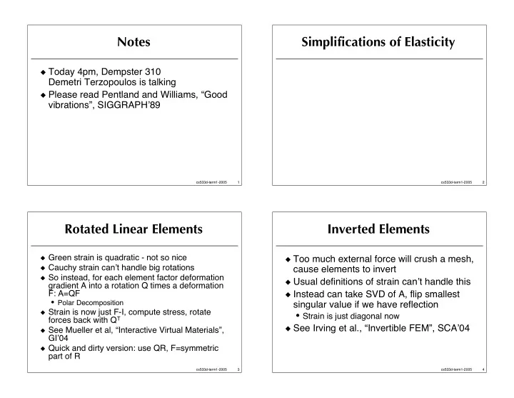
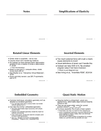
Notes Simplifications of Elasticity � Today 4pm, Dempster 310 Demetri Terzopoulos is talking � Please read Pentland and Williams, “Good vibrations”, SIGGRAPH � 89 cs533d-term1-2005 1 cs533d-term1-2005 2 Rotated Linear Elements Inverted Elements � Green strain is quadratic - not so nice � Too much external force will crush a mesh, � Cauchy strain can � t handle big rotations cause elements to invert � So instead, for each element factor deformation � Usual definitions of strain can � t handle this gradient A into a rotation Q times a deformation F: A=QF � Instead can take SVD of A, flip smallest • Polar Decomposition singular value if we have reflection � Strain is now just F-I, compute stress, rotate • Strain is just diagonal now forces back with Q T � See Irving et al., “Invertible FEM”, SCA � 04 � See Mueller et al, “Interactive Virtual Materials”, GI � 04 � Quick and dirty version: use QR, F=symmetric part of R cs533d-term1-2005 3 cs533d-term1-2005 4
Embedded Geometry Quasi-Static Motion � Common technique: simulation geometry isn � t as � Assume inertia is unimportant---given any detailed as rendered geometry applied force, deformable object almost instantly • E.g. simulate cloth with a coarse mesh, but render comes to rest smooth splines from it � Then we are quasi-static: solve for current � Can take this further: embedded geometry position where F internal +F external =0 • Simulate deformable object dynamics with simple � For linear elasticity, this is just a linear system coarse mesh • Potentially very fast, no need for time stepping etc. • Embed more detailed geometry inside the mesh for • Schur complement technique: assume external forces collision processing never applied to interior nodes, then can eliminate • Fast, looks good, avoids the need for complex (and them from the equation… finnicky) mesh generation Just left with a small system of equations for surface • See e.g. “Skeletal Animation of Deformable nodes (i.e. just the ones we actually can see) Characters," Popovic et al., SIGGRAPH � 02 cs533d-term1-2005 5 cs533d-term1-2005 6 Boundary Element Method Modal Dynamics � For quasi-static linear elasticity and a � See Pentland and Williams, “Good Vibrations”, homogeneous material, can set up PDE to SIGGRAPH � 89 eliminate interior unknowns---before � Again assume linear elasticity discretization � Equation of motion is Ma+Dv+Kx=F external • Very accurate and efficient! � M, K, and D are constant matrices • Essentially the limit of the Schur complement • M is the mass matrix (often diagonal) approach… • K is the stiffness matrix � See James & Pai, “ArtDefo…”, SIGGRAPH � 99 • D is the damping matrix: assume a multiple of K • For interactive rates, can actually do more: preinvert � This a large system of coupled ODE � s now BEM stiffness matrix � We can solve eigen problem to diagonalize and • Need to be smart about updating inverse when decouple into scalar ODE � s boundary conditions change… • M and K are symmetric, so no problems here - complete orthogonal basis of real eigenvectors cs533d-term1-2005 7 cs533d-term1-2005 8
Eigenstuff Decoupling into modes � Say U=(u 1 | u 2 | … | u 3n ) is a matrix with � Take y=U T x (so x=Uy) - decompose positions (and velocities, accelerations) into a sum of modes the columns the eigenvectors of M -1 K (also y = � M � 1 KUy � M � 1 DU ˙ y + M � 1 F ext U ˙ ˙ M -1 D) � Multiply by U T to decompose equations into modal • M -1 Ku i = � i u i and M -1 Du i = µ i u i components: • Assume � i are increasing y = � U T M � 1 KUy � U T M � 1 DU ˙ y + U T M � 1 F ext U T U ˙ ˙ • We know � 1 =…= � 6 =0 and µ 1 =…= µ 6 =0 ( ) y � diag µ i ( ) ˙ y + U T M � 1 F ext y = � diag � i ˙ ˙ (with u 1 , …, u 6 the rigid body modes) � So now we have 3n independent ODE � s • The rest are the deformation modes: the • If F ext is constant over the time step, can even write down exact larger that � i is, the smaller scale the mode is formula for each � Change equation of motion to this basis… cs533d-term1-2005 9 cs533d-term1-2005 10 Examining modes Throw out high frequencies � Mode i: � Only track a few low-frequency modes (5-10) i = � � i y i � µ i ˙ i + u i � M � 1 F ext ˙ ˙ y y � Time integration is blazingly fast! � Rigid body modes have zero eigenvalues, so just � Essentially reduced the degrees of freedom from depend on force thousands or millions down to 10 or so • Roughly speaking, rigid translations will take average of force, rigid rotations will take cross-product of force with positions • But keeping full geometry, just like embedded (torque) element approach • Better to handle these as rigid body… � Collision impulses need to be decomposed into � The large eigenvalues (large i) have small length scale, modes just like external forces oscillate (or damp) very fast • Visually irrelevant � Left with small eigenvalues being important cs533d-term1-2005 11 cs533d-term1-2005 12
Simplifying eigenproblem More savings � Low frequency modes not affected much by high � External forces (other than gravity, which frequency geometry is in the rigid body modes) rarely applied • And visually, difficult for observers to quantify if a mode is to interior, and we rarely see the interior actually accurate deformation � So we can use a very coarse mesh to get the modes, or even analytic solutions for a block of comparable mass � So just compute and store the boundary distribution particles � Or use a Rayleigh-Ritz approximation to the eigensystem (eigen-version of Galerkin FEM) • E.g. see James and Pai, “DyRT…”, • E.g. assume low frequency modes are made up of affine and SIGGRAPH � 02 -- did this in graphics quadratic deformations hardware! • [Do FEM, get eigenvectors to combine them] cs533d-term1-2005 13 cs533d-term1-2005 14 Inelasticity: Plasticity & Fracture Plasticity & Fracture � If material deforms too much, becomes permanently deformed: plasticity • Yield condition: when permanent deformation starts happening (“if stress is large enough”) • Elastic strain: deformation that can disappear in the absence of applied force • Plastic strain: permanent deformation accumulated since initial state • Total strain: total deformation since initial state • Plastic flow: when yield condition is met, how elastic strain is converted into plastic strain � Fracture: if material deforms too much, breaks • Fracture condition: “if stress is large enough” cs533d-term1-2005 15 cs533d-term1-2005 16
For springs (1D) Fracturing meshes (1D) � Go back to Terzopoulos and Fleischer � Breaking springs leads to volume loss: material disappears � Plasticity: change the rest length if the stress (tension) is too high � Solutions: • Maybe different yielding for compression and tension • Break at the nodes instead (look at average tension • Work hardening: make the yield condition more around a node instead of on a spring) stringent as material plastically flows � Note: recompute mass of copied node • Creep: let rest length settle towards current length at • Cut the spring in half, insert new nodes a given rate � Note: could cause CFL problems… � Fracture: break the spring if the stress is too • Virtual node algorithm high � Embed fractured geometry, copy the spring (see Molino et al. • Without plasticity: “brittle” “A Virtual Node Algorithm…” SIGGRAPH � 04) • With plasticity first: “ductile” cs533d-term1-2005 17 cs533d-term1-2005 18 Multi-Dimensional Plasticity Multi-Dimensional Yield criteria � Lots of complicated stuff happens when � Simplest model: total strain is sum of elastic and plastic parts: � = � e + � p materials yield • Metals: dislocations moving around � Stress only depends on elastic part • Polymers: molecules sliding against each other (so rest state includes plastic strain): • Etc. � = � ( � e ) � Difficult to characterize exactly when plasticity � If � is too big, we yield, and transfer some (yielding) starts • Work hardening etc. mean it changes all the time too of � e into � p so that � is acceptably small � Approximations needed • Big two: Tresca and Von Mises cs533d-term1-2005 19 cs533d-term1-2005 20
Recommend


More recommend
Explore More Topics
Stay informed with curated content and fresh updates.