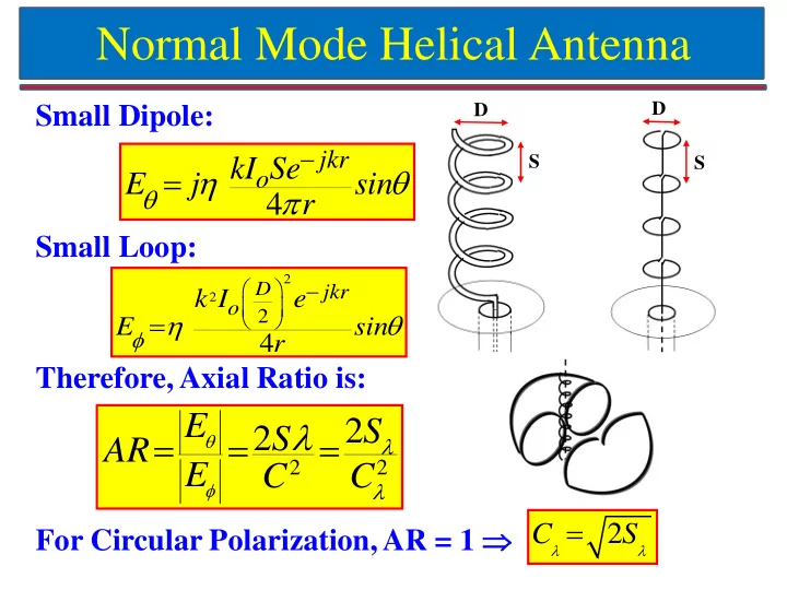
Normal Mode Helical Antenna D D Small Dipole: jkr S kI Se S - PowerPoint PPT Presentation
Normal Mode Helical Antenna D D Small Dipole: jkr S kI Se S o E j sin 4 r Small Loop: 2 D jkr k I e 2 o 2 E sin 4 r Therefore, Axial Ratio
Normal Mode Helical Antenna D D Small Dipole: jkr S kI Se S o E j sin 4 r Small Loop: 2 D jkr k I e 2 o 2 E sin 4 r Therefore, Axial Ratio is: E 2 S 2 S AR 2 2 E C C For Circular Polarization, AR = 1 2 C S
Design of Normal Mode Helical Antenna For Infinite Ground Plane: Wire length ≈ λ / 4 – text book > λ / 4 – in reality Radiation Resistance (R s ) 2 Iav 1(790) 2 R h R 0.6 s Io s 2 Axial Ratio (AR) 2 AR = 2 S λ / C λ = 2x0.01/0.04 2 = 12.5 = 21.94 dB Feed is tapped after one turn for impedance matching
Normal Mode Helical Antenna (NMHA) on Small Circular Ground Plane
NMHA Design on Small Circular Ground Plane Resonance Frequency 1.8 GHz Wavelength 166 mm Spacing = 0.027λ 4.5 mm Diameter of Helix = 0.033λ 5.5 mm No of Turns (N) 7 Pitch Angle ( α) 14.6 Degree Length of Wire = 0.75λ 124.5 mm
Effect of Ground Plane Size on NMHA As ground plane radius increases from λ/30 to λ/20, resonance frequency decreases and the input impedance curve shifts upward. NMHA designed for 1.8 GHz and r wire = 1.6 mm ( λ/100 )
Effect of Wire Radius on NMHA As radius of wire decreases from λ/80 to λ/120, its inductance increases so resonance frequency of NMHA decreases and its input impedance curve shifts upward (inductive region). NMHA designed for 1.8 GHz and r g = 5.5 mm ( λ/30 )
Effect of Wire Radius on Bandwidth of NMHA
Fabricated NMHA on Small Ground Plane and its Results
Horn Antennas Prof. Girish Kumar Electrical Engineering Department, IIT Bombay gkumar@ee.iitb.ac.in (022) 2576 7436
Horn Antennas E-Plane Sectoral Horn H-Plane Sectoral Horn TE 10 mode in Rectangular Waveguide Pyramidal Horn Conical Horn
Rectangular Waveguide a b TE 10 mode in Rectangular Waveguide For Fundamental TE 10 mode: E-Field varies sinusoidally along ‘a’ and is uniform along ‘b’ X-Band Waveguide WR90 (8.4 to 12.4 GHz): a = 0.9” and b = 0.4” Cut-off Wavelength = 2a = 2 x 0.9 x 2.54 = 4.572 cm Cut-off Frequency = 3 x 10 10 / 4.572 = 6.56 GHz
E-Plane Sectoral Horn Antenna
E-Plane Sectoral Horn: Side View ≈
E-Plane Sectoral Horn: Directivity Curve ρ 1 Max. Directivity: 6 10 20 100 b 1 3.46 4.47 6.32 14.14
E-Plane Sectoral Horn: Max. Phase Error Maximum Directivity occurs when Maximum Phase error occurs when y’ = b 1 / 2 δ max = 2πs, where ≈ which gives ‘s’ approximately equal to: δ max = 90 ° Phase Error too high: Not Recommended
E-Plane Sectoral: Universal Pattern E-Field for s = 1/4 ( δ max = 90 ° ) E-Field for s = 1/8 ( δ max = 45 ° ) - Recommended
H-Plane Sectoral Horn Antenna Maximum Phase δ max = 2πt, where error at x’ = a 1 / 2
H-Plane Sectoral Horn: Directivity Curve Max. Directivity: ρ 2 6 10 20 100 a 1 3 λρ 2 a 1 4.24 5.48 7.75 17.32
H-Plane Sectoral Horn: Max. Phase Error Maximum Directivity occurs when a 1 3 λρ 2 Maximum Phase error occurs when x’ = a 1 / 2 δ max = 2πt, where which gives ‘t’ approximately equal to: δ max = 135 ° Phase Error too high: Not Recommended
H-Plane Sectoral: Universal Pattern Recommended E-Field for t = 1/4 ( δ max = 90 ° ) max. phase E-Field for t = 1/8 ( δ max = 45 ° ) error between 45 ° and 90 °
Pyramidal Horn Antenna Top View Side View
Pyramidal Horn Antenna Condition for Physical Realization:
Pyramidal Horn: Design Procedure Alternatively Directivity of Pyramidal Horn Antenna can be obtained using Directivity curves for E-and H-Planes Sectoral Horn antenna
Pyramidal Horn Design Steps
Pyramidal Horn Design: Example
Pyramidal Horn Design: Example (Contd.)
Pyramidal Horn Design: Example (Contd.)
Optimum Dimensions vs. Directivity L λ a Hλ a Eλ Gain (dBi)
Recommend


More recommend
Explore More Topics
Stay informed with curated content and fresh updates.