
LA-UR-01-6658 Mixing Between Two Compressing Cylinders Steven H. Batha Los Alamos National Laboratory K. W. Parker, # C. W. Barnes,* A. M. Dunne, # N. E. Lanier,* G. R. Magelssen,* T. J. Murphy,* S. D. Rothman, # J. M. Scott,* and D. L. Youngs # *LANL, # AWE 8th International Workshop on Compressible Turbulence and Mix Poster E5; Pasadena, CA December 11, 2001
Abstract • Foam-filled cylinders have been imploded by the OMEGA laser at the University of Rochester. A marker layer of heavier material is placed between the foam and the outside ablator. The marker layer is hydrodynamically unstable when a strong shock passes through both these interfaces and the marker layer material mixes into the foam and the ablator. • These experiments thus measure mix in the compressible, convergent, miscible, strong-shock regime. These experiments are being extended by placing a solid cylinder at the center of the foam, forming a set of concentric cylinders separated by foam. The initial shock converges on the central cylinder and then rebounds and expands. The shock is predicted to create even more mixing of the marker layer as it traverses the previously mixed region. We present experimental measurements of this configuration. • LA-UR-01-2575: This document was produced by the Los Alamos National Laboratory under the auspices of the United States Department of Energy under contract no. W-7405-ENG-36. LA-UR-01-6658 12/4/01 2/16
Why direct-drive cylindrical implosions? • Purpose – Study Richtmyer-Meshkov (RM) instability in compressible, convergent, miscible systems undergoing strong shocks – Examine mixing due to reflectance of a shock from the center (reshock) • Method – Implode cylinder with an unstable interface and measure resulting mix – Diagnostic advantages, fewer ends to affect experiment, convergent • This poster presents initial experimental results • See Kenny Parker’s poster for design information – “Computational Modeling of 2 – Shell Cylindrical Implosions with Mix” for design information LA-UR-01-6658 12/4/01 3/16
We have established a useful, laser- based test bed for mix experiments • Implode cylinder with thick ablator with 1-ns square pulse direct laser irradiation • Hydrodynamically unstable at plastic/Au and Au/foam interfaces • Backlight with x rays through cylinder • Measure radial extent of “mix layer” of Au into adjacent materials • 1D convergent experiment with Mach number ≈ ≈ 20 (pre-shock; Mach ≈ ≈ ≈ ≈ 5 ≈ ≈ post-shock), convergence ≈ ≈ 4, ≈ ≈ Pressure > 45 Mbars, Reynold’s ≈ 10 6 * number ≈ ≈ ≈ *Galmiche and Gauthier, Jpn. J. Appl. Phys. 35 (1996) 4516 LA-UR-01-6658 12/4/01 4/16
We use the Omega laser at the The OMEGA laser is the world’s most powerful UV laser University of Rochester for fusion research Laser bay Target bay • 60 beams • > 30 kJ UV on target • 1%–2% irradiation nonuniformity • Flexible pulse shaping LA-UR-01-6658 12/4/01 • Short shot cycle ( 1 h ) 5/16 TC2998p
Complete Imaging X-Ray Streak Camera Diagnostic Coverage SSC1 Streak of Backlighter Available • Diagnostics for shot 13315 XRFC4 Axial Radiography XRFC1 View of Backlighter LLE X-Ray Spectrometer Streak of Chlorine Emission XRFC3 Transverse View of Self-Emission LA-UR-01-6658 12/4/01 6/16
Double cylinder adds an inner shell • Al or Cu wire in center provides a hard reflector for the main shock • Wire: 700 µm long • Marker layer: 500 µm long Center Shell Marker Layer CH and Foam LA-UR-01-6658 12/4/01 7/16
LA-UR-01-6658 12/4/01 8/16
Intershell region undergoes strong shocks and mix Ablator Marker Radius (cm) Region of Interest Foam (60 mg/cc) Cu core Time (ns) LA-UR-01-6658 12/4/01 9/16
Time/space regions of interest • Proof-of-principle experiment based on low-mix design • Solid, centered Al “shell” • Want to diagnose mix between shells Ablator Marker Radius (cm) Foam Region of Interest (60 mg/cc) Al core Time (ns) LA-UR-01-6658 12/4/01 10/16
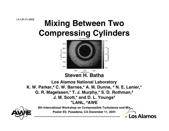
Intershell region clearly visible Cu center shell (opaque) Foam between shells (transparent) Ni marker layer (opaque) Plastic ablator (transparent) • Marker mixes into foam and ablator • Radiograph at 6.9 keV (Fe K-shell) • Backlighter intensity varies smoothly across image LA-UR-01-6658 12/4/01 11/16
Radial lineout shows different regions • Average radial transmission profile Cu center shell (opaque) Foam between shells (transparent) Ni marker layer (opaque) 0.025 2 2 6 1 9 _ 3 a 2 ) Exposure (ergs/cm Plastic ablator 0.020 (transparent) 0.015 0.010 0.005 0.000 0 100 200 300 400 S. H. Batha December 2, 2001 Radius (µm) LA-UR-01-6658 12/4/01 12/16
Compare double to single cylinders Rough-Au Outer Ablator Mix Region 50% Foam Core 0.025 2 ) 22619_3a Exposure (ergs/cm 0.020 Mix width: 144 ± 13 µm 0.015 50% 50% 0.010 0.005 50% 0.000 0 100 200 300 400 S. H. Batha Radius (µm) December 2, 2001 LA-UR-01-6658 12/4/01 13/16
Marker layer has expanded near peak compression 100 • Marker/inner shell 2 2 6 1 9 separation initially 290 µm Mix Width (µm) 80 60 • 4-µm-thick Ni marker 40 • Mix width ≈ ≈ 65 µm ≈ ≈ 20 0 2 3 4 5 S. H. Batha December 2, 2001 Time (ns) LA-UR-01-6658 12/4/01 14/16
Dynamics of implosion as expected • Little change in outer- shell radius seen over PRELIMINARY 400 ps 250 2 2 6 1 9 Mix Width (µm) 200 Mix Width • Central shell has not 150 expanded (initial radius 100 ≈ 140 µm) ≈ ≈ ≈ Inner Cylinder Radius (µm) 50 Inner Mixing Radius (µm) Outer Mixing Radius (µm) 0 3 4 5 S. H. Batha December 2, 2001 Time (ns) LA-UR-01-6658 12/4/01 15/16
Conclusions • Double-cylinder targets can be built and fielded • Excellent radiographic data of intershell region obtained • Central shell does not expand during experiment • Mixing observed • See Kenny Parker’s poster (C28) LA-UR-01-6658 12/4/01 16/16
Recommend
More recommend