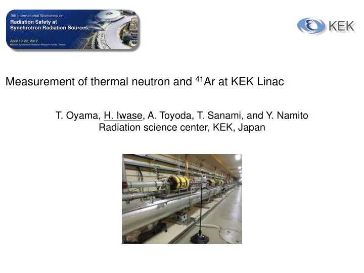

KEK Measurement of thermal neutron and 41 Ar at KEK Linac T. Oyama, H. Iwase, A. Toyoda, T. Sanami, and Y. Namito Radiation science center, KEK, Japan
1. Purpose - Air activation by electron accelerator e - facilities have less air activation than hadron facilities - However modern e - accelerators will have higher power - More accurate evaluation of air activation is required - ratio of evaluated air activation production Nuclide Halflife Reaction Threshold (MeV). in whole linac tunnel 12.3y 53.3d 20.4m 9.96m 2.04m 37.2m 55.5m 1.82h thermal neutron a pair of pump and stack Experimental study on 41 Ar production - 2
PFAR 1.2 KEK Linac SUPE 6.5GeV R e- KEKB e- PF 2.5Ge V e+ Dumping e- Ring e+ maximum beam power e- Linac e- 10 GeV 625nA ~ 6.3kW on target (future x1.5) e- 3.3 GeV 800nA ~ 2.6kW e+ production target 3
1.3 KEK-Linac positron production target Beam e- 3.3 GeV, 100 nA Target W 1cm and other components (thick target) T. Kamitani (KEK) ~15cm cabity e- by RF gun york target 4
Target shield final ver. (3.3 GeV 1250nA e-) Target shield 2015 (Radsynch15) KEK controlled controlled KEK controlled (max 1.5 uSv/h) controlled Distance 430cm Distance 700cm Distance 555cm Concrete 250cm Concrete 400cm Concrete 320cm Iron 59cm Iron 72cm Iron 70cm ground level public (max klystron room 0.2 uSv/h) lystron room controlled controlled (max 20 uSv/h) concrete concrete keep out keep out
2. Methods 6
2.1 Experiment-A - 40 Ar gas direct irradiation Target 3.3GeV e- X Y Z (0m) (15m) (35m) 40 Ar gas packages were set in tunnel at positions of X, Y, and Z 7
2.2 Experiment-B - Thermal neutron fluence Φ Target 3.3GeV Z X Y e- (35m (0m) (15m) ) Thermal neutron fluence Φ in tunnel was measured by the Gold foil activation with/without Cadmium cover JENDL-4.0 JENDL-4.0 8
2.3 Experiment-C - Thermal neutron spatial distribution target e- 30m Thermal neutron fluence Φ in tunnel was measured by the Gold method at different positions of upstream and downstream from the target 9
3 Result1 - Experiments A and B Target 3.3GeV Z X Y e- (35m (0m) (15m) ) A: Ar gas B: Gold foil (Bq/cm 3 /kW) (Bq/cm 3 /kW) X(0m) 9.2 ± 1.4 9.2 ± 0.7 kW) Y(15m) 0.73 ± 0.14 0.56 ± 0.034 Z(35m) 0.077 ± 0.016 0.038 ± 0.0015 10
3.2 Result2 - Thermal neutron spatial distribution target e- 30m measurements PHITS 3D Monte Carlo ± 30m from target simulation covers 99% of total integration ratio to total range amount ± 15m 91% ± 20m 96% 11 ± 30m 99%
40 Ar (n, γ) 41 Ar reaction Neutron energy spectrum in tunnel around target PHITS capture Monte Carlo simulation 41Ar productions induced below 1 eV neutron (10-6 MeV) account for 98.7% of total 12
Gold foil can be used instead of Gas? • Experiment-C indicates that thermal neutrons distribute in certain range of ± 20m (or ± 30m) • The discrepancy of the Experiment-A(Gas) and B (Gold foil) can negligible in case to obtain integral number of 41 Ar production • the answer is yes
Neutron energy spectra from 20cm Fe target by 1 GeV e- Thermal neutron source around KEK Linac target High energy GDR thermal neutron ( <1eV) track length plot around the target 14
Comparison to theoretical evaluation Standard method to estimate thermal neutron fluence for electron accelerator (1) GDR neutron production Yn by Mao ’ s formula Y n = 8 × 10 −6 E 0 ( Z 0.5 + 0.12Z 1.5 − 0.001Z 2.5 ) where Yn GDR neutron production per e-, E0 e- energy (MeV), and Z atomic number of thick target. If Z=74(W) Yn=1.0, and Z=29(Cu) Yn=0.52. => 0.76 (n/e-) in average (2) GDR neutron reduction R by components (shielding effect) I t is difficult to predict by hand-calculation. For example set R to 1/2. => R Yn = 0.76/2 = 0.38 (n/e-) (3) Neutron thermalization formula by Patterson Φ = C R Yn / S where C is a constant of 1.25, and S is total area of the tunnel (cm2) Φ = 2.1e4 (1/cm 2/nA/sec) compared to experiment (4.42e-3) calculation agrees well => 41Ar = 4.95e-3 (Bq/cm3/nA) 15 (due to (2) is estimated by experience)
5. Conclusion 16
Recommend
More recommend