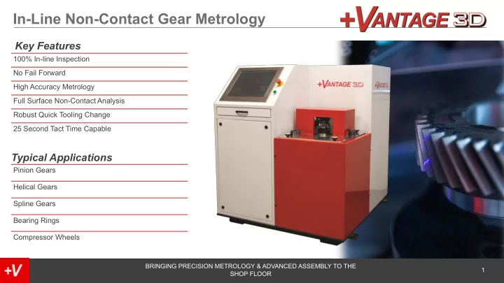

In-Line Non-Contact Gear Metrology Key Features 100% In-line Inspection No Fail Forward High Accuracy Metrology Full Surface Non-Contact Analysis Robust Quick Tooling Change 25 Second Tact Time Capable Typical Applications Pinion Gears Helical Gears Spline Gears Bearing Rings Compressor Wheels BRINGING PRECISION METROLOGY & ADVANCED ASSEMBLY TO THE 1 SHOP FLOOR
Standard Machine Overview - 100% inline dimensional and geometrical inspection - 30-60 second cycle time ( Cycle Time increases as the Diameter of the gear increases ) - <1µm Repeatability - Inspect gears < 250mm Diameter . * Larger gears CAN be inspected with an upgraded machine for additional price. (requires additional mechanical design) - Allen Bradley PLC – Easy integration with Customer line and Plant Data System - 10 Minute Part Changeover - AGMA , ISO , and DIN standards for accuracy grading. - Laser Profile Sensors calibrated to a common coordinate volume - Rotary Air Bearing <20nm runout - +V3D Core Software – Calibrates Sensors into a common coordinate system and generates point cloud - Metrolog Inspection Software – Pulls in point cloud, compares to CAD model and generates results - +V3D Comm – Primary control software that synchronizes the rotary motion with the sensors, directs data traffic and communicates status to PLC
Additional Part Types -The machine is designed with interchangeable tooling plates for different parts. -Part type changeover is a 10-minute process: 1. Remove sensors 2. Replace Tooling Plate 3. Replace sensors 4. Calibrate sensors 5. Ready to run -Additional Part type cost includes: -Metrolog Inspection Software Programming -Sensor Position and Tooling Plate design -Calibration of gage (Artifact Design and Certification)
Lab Qualification Prior to accepting a PO, we will verify feasibility using our lab system to make sure the sensors collect reliable data from the surface of the gear flanks. Our lab system is also used to determine the optimal sensor locations to implement in the mechanical design of the final machine. Upon request a correlation study can be done before ordering a machine, we need to manufacture and certify an artifact to calibrate the sensors, program an inspection in Metrolog, and run a study.
Create Gear Model We will utilize a Gear Module to create a CADModel for the inspections. A provided model is not sufficient to perform inspection in Metrolog. The Model must be created within the software with information from the part print. The Gear Module has Pitch information as well as Helix and Profile locations built into its generated Model. *Bevel Gears still need development 10/17/19
Measurement Method Metrolog inspection software aligns the Cloud of points measured to the generated CAD model using predefined datum surfaces. Cylindrical regions of interest are established along the profile and helix to compare the data points with respect to the nominal CAD surface. We can measure at multiple diameters and levels. Profile Helix Helix inspection
Helical Inspeciton Mean helix line Mean helix line Parallels enclosing the actual helix profile Helix deviation(lead): Total helix Helix form deviation Helix slope deviation deviation
Profile Inspection Mean profile line Mean profile line Parallels enclosing the actual involute profile Pitch deviation: Total profile Profile form deviation Profile slope deviation deviation
Recommend
More recommend